Operating & Mounting instructions – 8 074 143.03/03 – Page 79
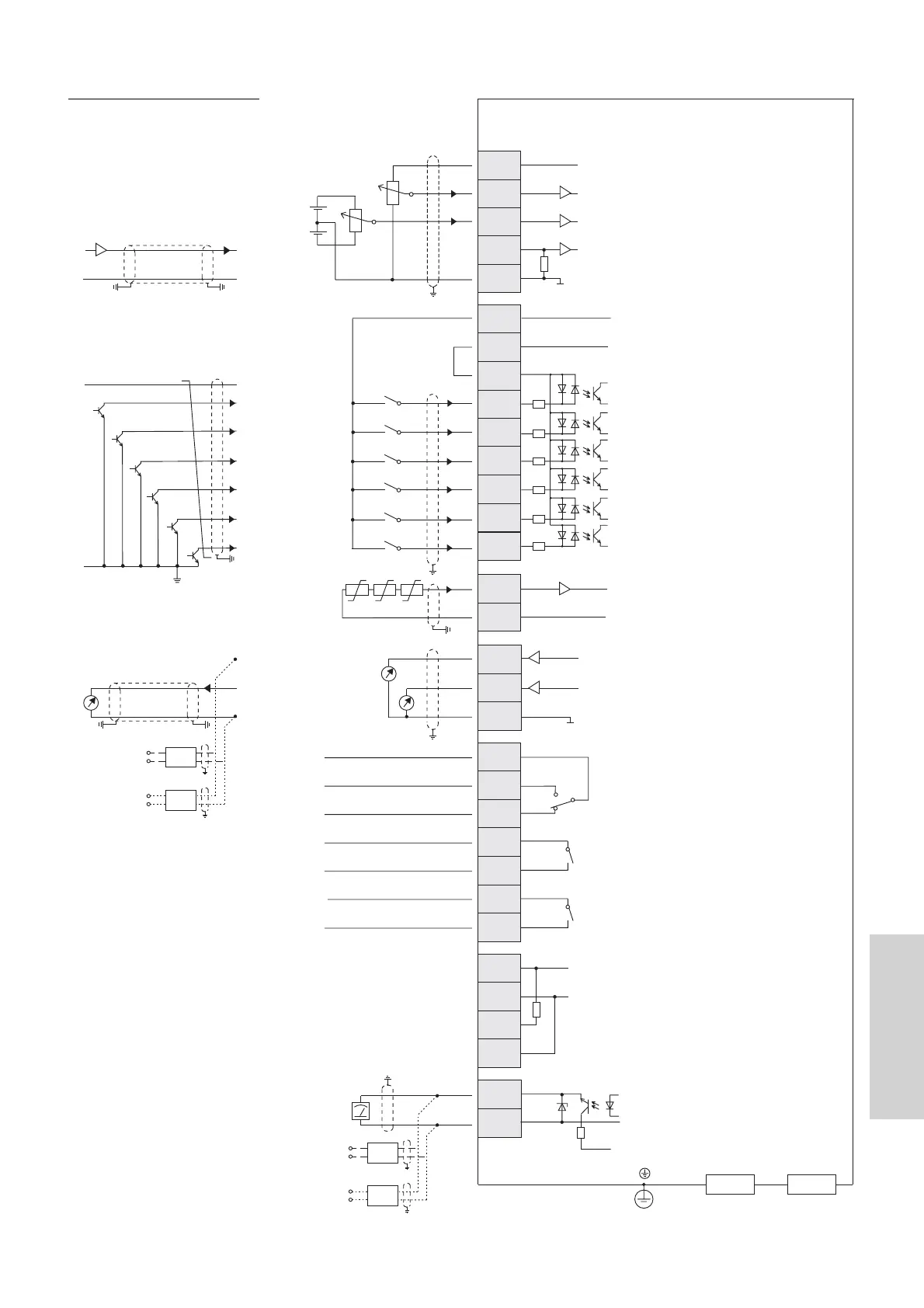
Connection
Common (nicht erden! / don’t earth!)
+24V Referenz / reference; 100 mA
Digital input common
3
CM1
TH
4
2
-10...+10V Analogeingang / analogue input
Masse / ground
0...+10V Analogeingang / analogue input
+10V Referenz / reference; 20 mA
O2
L
O
H
OI
1 bis/to 2kOhm
5
1
FW
PLC
CM1
P24
Digitaleingang 5 (REV) / digital input 5 (REV)
Digitaleingang 4 (CF1) / digital input 4 (CF1)
Digitaleingang 3 (CF2) / digital input 3 (CF2)
Digitaleingang 2 (AT) / digital input 2 (AT)
Digitaleingang 1 (RES) / digital input 1 (RES)
Common (nicht erden! / don’t earth!)
Common (nicht erden! / don’t earth!)
Thermistoreingang / thermistor input
0...10V Analogausg. / 0...10V analogue output
4...20mAAnalogausg. / 4...20mA analogue outp.
Masse / ground
Rechtslauf-Befehl / forward command
potentialfreie
Signalkontakte/
potential-free
signal contacts
4..20mAAnalogeingang / analogue input
0...10 V
potentialfreier Meldeausgang /
potentialfreier Meldeausgang /
potentialfreier Meldeausgang /
voltage-free signal output
voltage-free signal output
voltage-free signal output
0 ... 10 V
4...20mA
4...20mA**
4...20mA*
As an alternative of the 0...10V signal
the option with a
4...20mA signal or the option
with a 0...20mA
signal can be used.
>pDRIVE< TV5
>pDRIVE< TV6
Alternativ zum 0...10V Signal kann
wahlweise die Option
mit einem 4...20mA Signal oder die
Option mit einem
0...20mA Signal verwendet werden.
>pDRIVE< TV5
>pDRIVE< TV6
**)
**)
0...20mA**
0...20mA*
0...10V
0...10V
Interne Verdrahtung der Steuerklemmen /
internal wiring of the control terminals
Externe Verdrahtung / external wiring
FM
CM1
TV6
TV6
TV5
TV5
SP
RP
SN
SN
11C
11A
AL2
AL1
AL0
AM
12C
L
12A
AMI
PWM
+24V
Relaisausgang (AL) * / Relay output (AL) *
Relaisausgang 11 f = fsoll * /
relay output 11 f = fref *
Relaisausgang 12 Betrieb * /
relay output 12 operation *
Serielle Schnittstelle RS485 /
serial interface RS485
Option 1 Option 2
Kaltleiter /
Thermistor
4...20mA
4...20mA
+24V
NPN or PNP
Open-Collector
0V
Darstellung der Relaisausgänge im
ausgeschalteten Zustand
(Werkseinstellung)
*)
Figure shows relay outputs at
factory default (inverter switched off)
*)
 Loading...