Operating & Mounting instructions – 8 074 143.03/03 – Page 46
C021
Function of relay 11 VIC 00 to 13 01
C022
Function of relay 12 VIC 00 to 13 00
C026
Function of relay AL VIC 00 to 13 05
The programmable relay outputs (terminals 11 and 12 and also AL) can be programmed using
parameters C021, C022 and C026. The following functions can be programmed:
Setting Short-cut Function
00 RUN Operation
01 FA1 „Reference value arrival“ - signal
02 FA2 „Frequency exceeded“ - signal (C042, C043)
03 OL Overload message
04 OD PID deviation too high
05 AL Error message
06 FA3 „Frequency arrival“ - signal (C042, C043)
08 IP Mains failure
09 UV Undervoltage
11 RNT Operating hours motor exceeded (b034)
12 ONT Operating hours inverter exceeded (b034)
13 THM Temperature alarm (C061)
Function: RRUN C021, CC022 oor CC026 == 00 RRUN ““Operation”
Digital outputs
Output terminals
Note:
If the frequency value of the inverter is smaller than the start frequency (which is set with
parameter b082), there is no “Operation”-signal (RUN).
Function: FFA1 C021, CC022 oor CC026 == 001 FA1 “Ref. vvalue aarrival”
Function: FFA2 C021, CC022 oor CC026 == 002 FA2 “Frequency eexceeded”
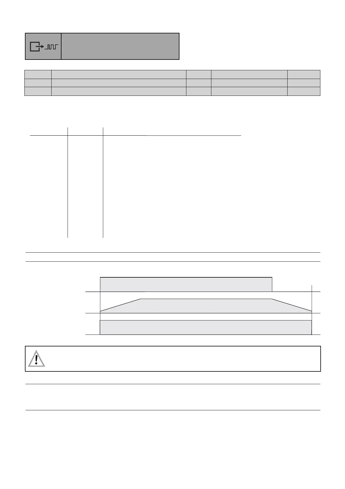
Function: FFA3 C021, CC022 oor CC026 == 006 FA3 “Frequency aarrival”
The frequency at which the signal is to be issued during acceleration is set using parameter C042
(hysteresis -0,5 Hz bis +1,5 Hz).
The frequency at which th signal is to be issued during deceleration is set using parameter C043
(hysteresis +0,5 Hz bis -1,5 Hz).
 Loading...