Operating & Mounting instructions – 8 074 143.03/03 – Page 84
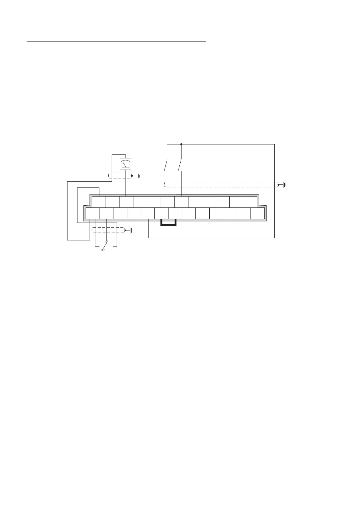
Operation via analogue reference value 0...10 V
Following parameters have to be changed:
A001 = 01 Reference value via terminal
A002 = 01 Control command via digital input
F002 = 10 s Adjust acceleration time
F003 = 10 s Adjust deceleration time
C005 = 01 REV Start reverse on digital input 5
b080 = 180 Adjustment of analog display
L
H
O
O2
OI
AM
AMI
FM
P24
TH
PLC
FW
CM1
5
12C
4
12A
3
11C
2
11A
1
ALO
AL1
AL2
Start RL / FWD
Start LL / REV
Meßgerät / measuring device
0...10 V, 1 mA
Potentiometer
1...2 k
Start/Stop is realised via the digital inputs FW and 5. If both terminals are closed at the same time, a
Stop command is issued to the frequency inverter.
The required frequency can be set by turning the external potentiometer.
In addition, a test device to display the actual frequency value was also built into this example on the
analog output AM. If parameter C028 is set to 01, the motor current is displayed on the test device.
The output signal can be adjusted using parameter b080.
 Loading...