Operating & Mounting instructions – 8 074 143.03/03 – Page 96
AMF 450/12 AMF 450/48 AMF 450/90
Mains voltage 3 x 380...500 V 3 x 380...500 V 3 x 380...500 V
Nominal current 12 A 48 A 90 A
Overload capacity 20 % for 60 s 20 % for 60 s 20 % for 60 s
Losses max. 150 W max. 250 W max. 350 W
Protection degree IP00 IP00 IP00
Terminals VBG4 VBG4 VBG4
Cable diameter max. 10 mm
2
max. 16 mm
2
∅11 mm
Weight approx. 5,5 kg approx. 8,0 kg approx. 10 kg
Protection Thermoclixon 120° Thermoclixon 120° Thermoclixon 120°
Contact N.C. N.C. N.C.
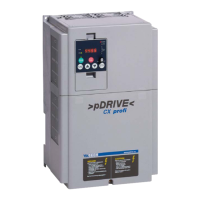
AMF 450/12: AMF 450/48:
AMF 450/90:
The choke has to be connected directly to the output terminals (U,V, W) of the frequency inverter.
In case of overtemperature of the choke caused by too high switching frequencies and/or too long
cables, the inverter will trip with "external trip".
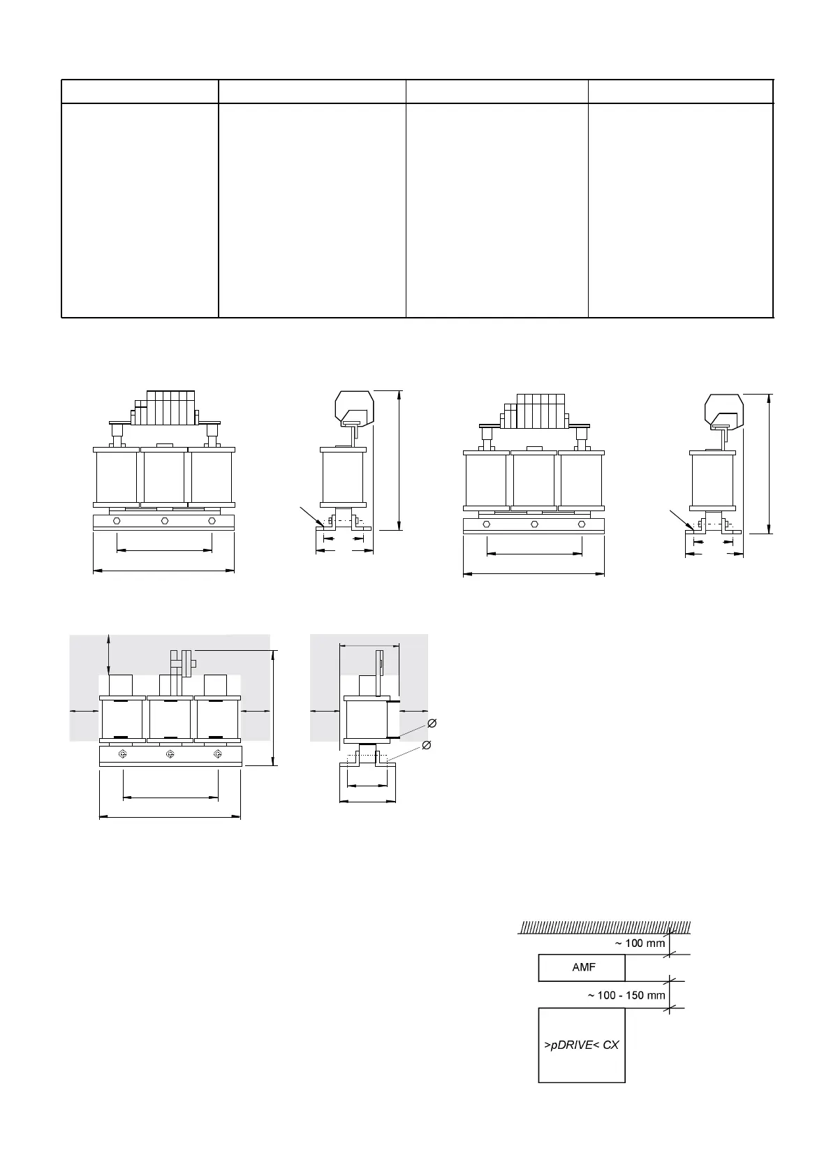
To prevent the cooling air of the frequency
inverter against pre-heating and to cool the
choke, it is recommended to place the choke
appr. 100...150 mm above the frequency
inverter.
 Loading...