Operating & Mounting instructions – 8 074 143.03/03 – Page 39
Parameters
Explanations of the functions for the digital inputs
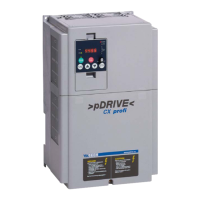
Start/Stop via switch contacts:
When the contacts are closed, a Start command is
issued in the right direction (acceleration on
gradient), when open, a stop command is issued
(deceleration on gradient). The simultaneous
closing of Start forward and Start reverse also
issues a Stop command to the inverter.
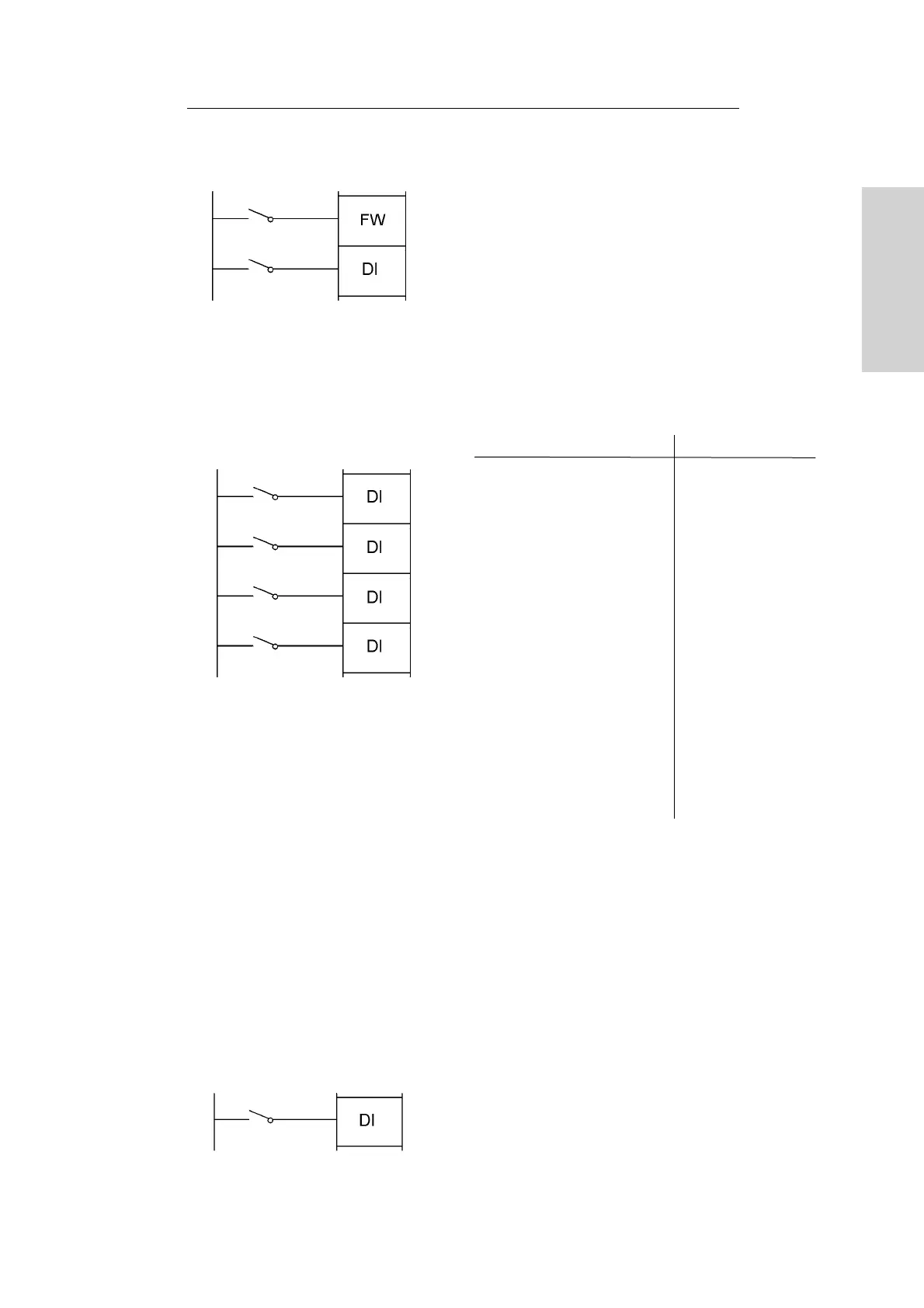
Multispeeds (“binary” function):
The multispeeds (maximum 15) are selected via
the signals CF1...4 according to the table:
CF1 CF2 CF3 CF4 Reference value
0 0 0 0 analog value
1 0 0 0 1 (A021)
0 1 0 0 2 (A022)
1 1 0 0 3 (A023)
0 0 1 0 4 (A024)
1 0 1 0 5 (A025)
0 1 1 0 6 (A026)
1 1 1 0 7 (A027)
0 0 0 1 8 (A028)
1 0 0 1 9 (A029)
0 1 0 1 10 (A030)
1 1 0 1 11 (A031)
0 0 1 1 12 (A032)
1 0 1 1 13 (A033)
0 1 1 1 14 (A034)
1 1 1 1 15 (A035)
The number of digital inputs to be programmed
depends on the number of multispeeds actually
needed. The multispeeds are programmed in
parameter group A. The multispeeds are pure
reference values without any Start/Stop
commands.
Therefore, Parameter A001 “Method of speed
command” must be set to 01 “control terminals” !
Jog mode:
If the Jog command is activated, the inverter
accelerates the motor with the fastest possible
acceleration time to the set jog frequency A038.
00 Start FWD
01 Start REV
02 Fix A
03 Fix B
04 Fix C
05 Fix D
06 Jog mode
 Loading...