5-17
E
POWR
CONTROL UNIT
CONTROL UNIT
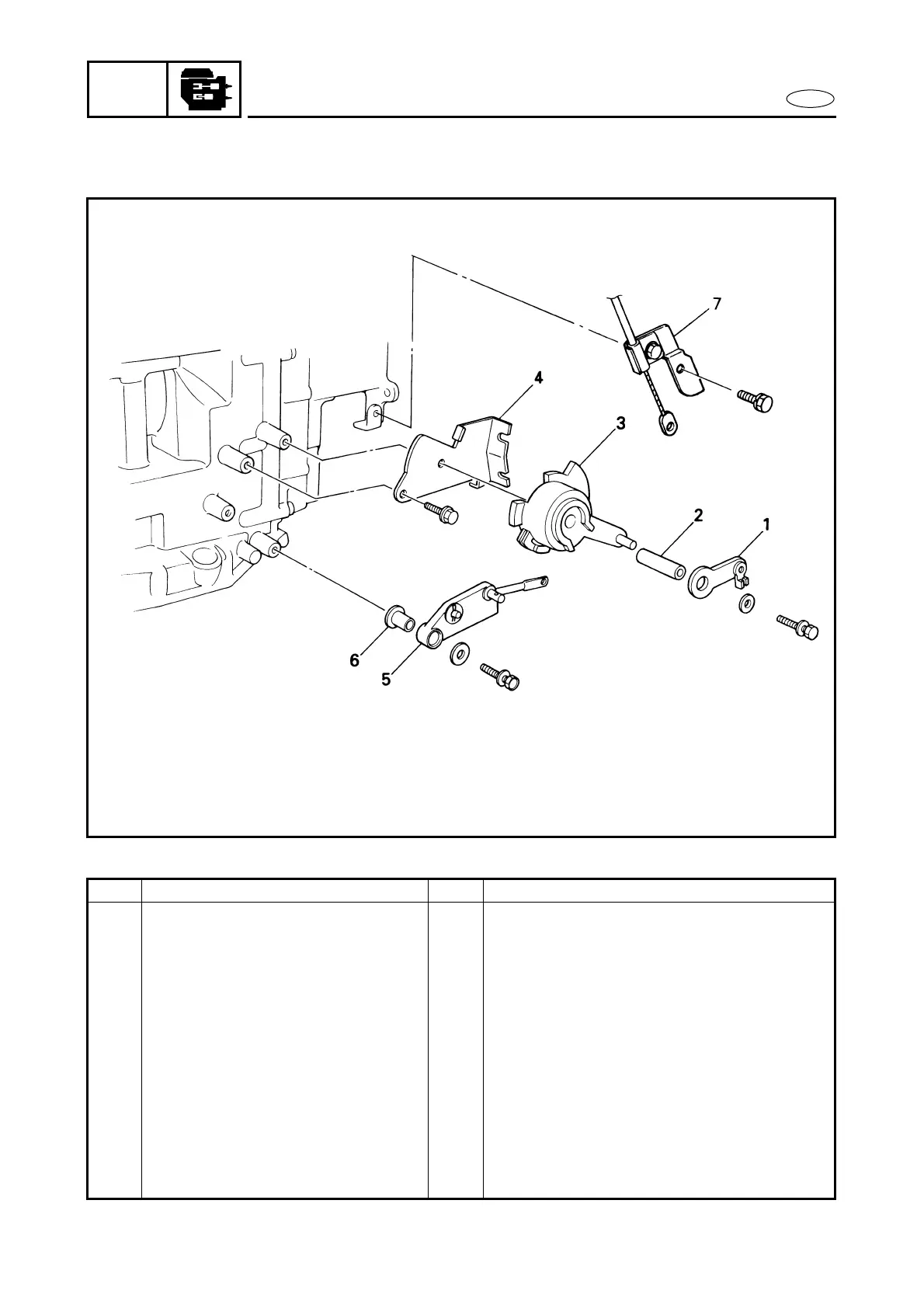
EXPLODED DIAGRAM
REMOVAL AND INSTALLATION CHART
Step Procedure/Part name Q’ty Service points
CONTROL UNIT REMOVAL Follow the left “Step” for removal.
Throttle link rod Refer to “CARBURETOR UNIT” in chapter
4.
Shift link rod Refer to “POWER UNIT”.
1 Throttle control lever 1
2 Spacer 1
3 Throttle control cam 1
4 Throttle control cam bracket 1
5 Shift link rod assy. 1
6 Collar 1
7 Start-in-gear protection device
wire assy. (MH)
1
Reverse the removal steps for installation.

 Loading...