5-18
E
POWR
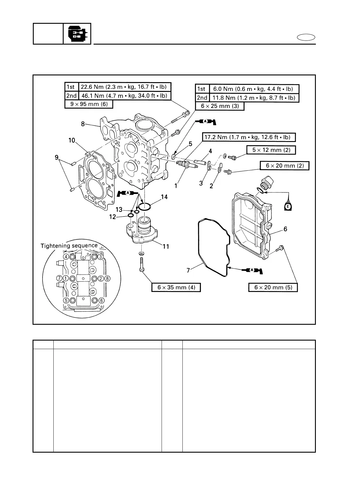
CYLINDER HEAD AND OIL PUMP
CYLINDER HEAD AND OIL PUMP
EXPLODED DIAGRAM
REMOVAL AND INSTALLATION CHART
Step Procedure/Part name Q’ty Service points
CYLINDER HEAD AND OIL PUMP
REMOVAL
Follow the left “Step” for removal.
Power unit Refer to “POWER UNIT”.
Driven sprocket Refer to “STATOR AND TIMING BELT”.
Ignition coil and rectifier/
regulator
Refer to “ELECTRICAL UNIT”.
1 Spark plug 2
2 Plate 2
3 Anode cover 2
4 Anode 2
5 Grommet 2
6 Cylinder head cover 1

 Loading...