5-33
E
POWR
CRANKCASE, CRANKSHAFT ASSY., AND
CYLINDER BODY
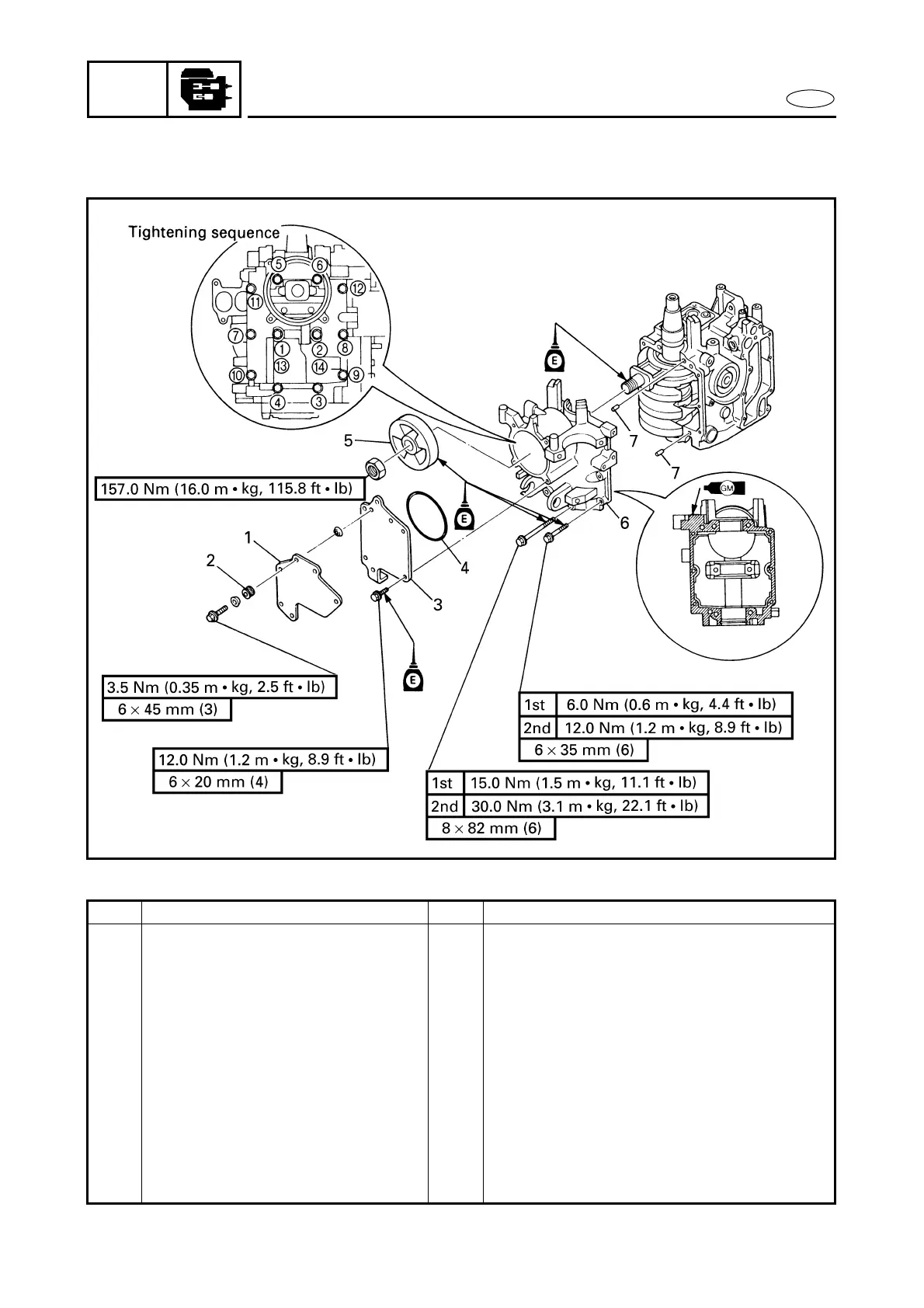
CRANKCASE, CRANKSHAFT ASSY., AND CYLINDER BODY
EXPLODED DIAGRAM
REMOVAL AND INSTALLATION CHART
Step Procedure/Part name Q’ty Service points
CRANKCASE REMOVAL Follow the left “Step” for removal.
Power unit Refer to “POWER UNIT”.
Stator Refer to “STATOR AND TIMING BELT”.
Electrical unit Refer to “ELECTRICAL UNIT”.
1 Bracket 1
2 Grommet 3
3 Piston cylinder cover 1
4 O-ring 1
5 Balancer piston 1
6 Crankcase 1
7 Dowel pin 2
Reverse the removal steps for installation.

 Loading...