7-7
E
BRKT
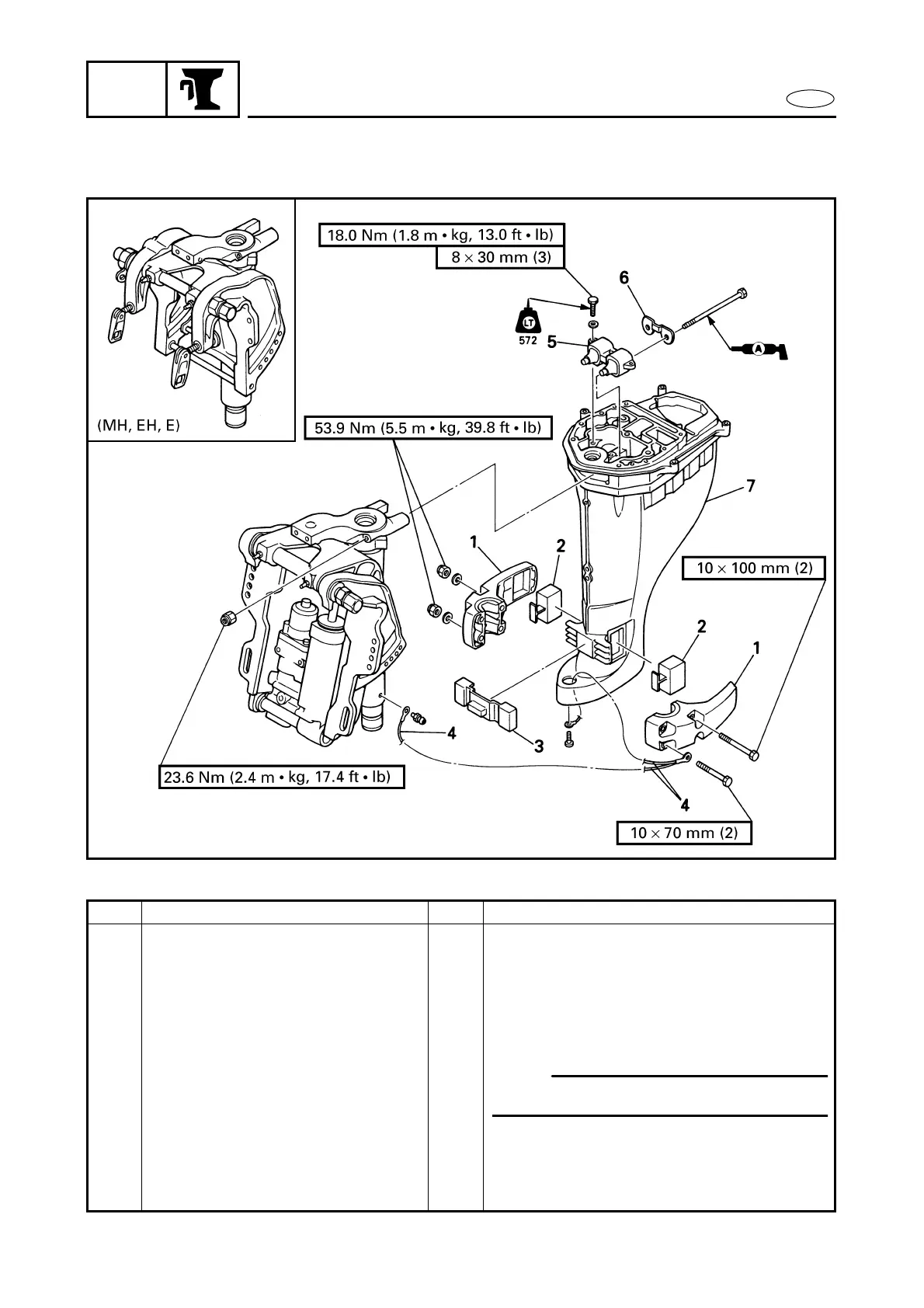
UPPER CASE ASSY.
UPPER CASE ASSY.
EXPLODED DIAGRAM
REMOVAL AND INSTALLATION CHART
Step Procedure/Part name Q’ty Service points
UPPER CASE ASSY. REMOVAL
Follow the left “Step” for removal.
Lower unit Refer to “LOWER UNIT” in chapter 6.
Bottom cowling Refer to “BOTTOM COWLING”.
1 Lower mount housing 2
2 Lower rubber damper (side) 2
3 Lower rubber damper (front) 1
4 Ground lead 1
5 Upper damper 1
6 Upper damper retaining plate 1
7 Upper case assy. 1
Reverse the removal steps for installation.
NOTE:
Remove the lead at three different points.

 Loading...