8-13
–+
ELEC
E
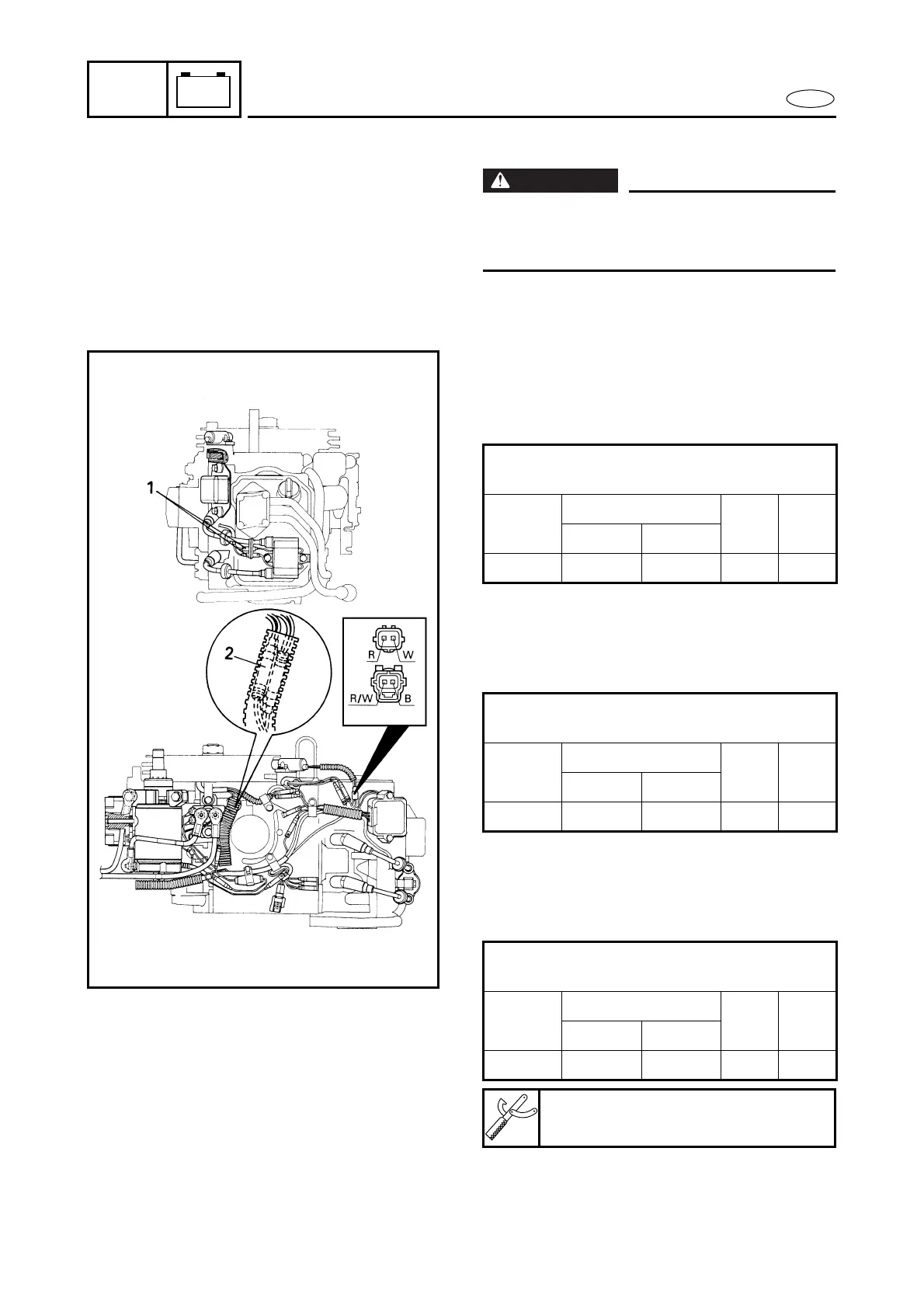
IGNITION SYSTEM
IGNITION SYSTEM PEAK VOLTAGE
WARNING
When checking the CDI unit, do not touch
any of the connections of the digital tester
leads.
1. Measure:
● CDI unit output peak voltage
Above specification → Replace the
ignition coil.
2. Measure:
● Charge coil output peak voltage
Below specification → Replace the
stator.
3. Measure:
● Pulser coil output peak voltage
Below specification → Replace the
pulser coil.
Output peak voltage:
B/W – O
r/min
Cranking
1500 3500
Opened Closed
V 200 180 190 190
Output peak voltage:
G/W – W/G
r/min
Cranking
1500 3500
Opened Closed
V 240 210 210 210
Output peak voltage:
R – W
r/min
Cranking
1500 3500
Opened Closed
V 90 90 210 240
Test harness:
YB-06768/90890-06768
 Loading...