7-1
E
BRKT
STEERING HANDLE
STEERING HANDLE
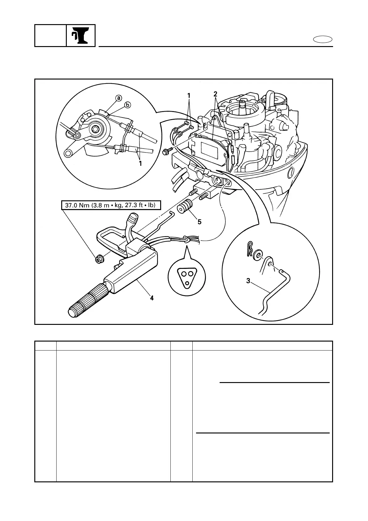
EXPLODED DIAGRAM
REMOVAL AND INSTALLATION CHART
Step Procedure/Part name Q’ty Service points
STEERING HANDLE REMOVAL
Follow the left “Step” for removal.
Flywheel magneto cover assy. Refer to “FLYWHEEL MAGNETO” in
chapter 5.
1 Throttle cable 2
2 Engine stop switch lead 2
3 Shift link rod 1
4 Steering handle assy. 1
5 Grommet 1
Reverse the removal steps for installation.
NOTE:
When adjusting the throttle cables, make
sure the throttle control cam stopper a
touches the bracket stopper b (when the
throttle is fully-opened) and then tighten
the locknuts.

 Loading...