8-10
–+
ELEC
E
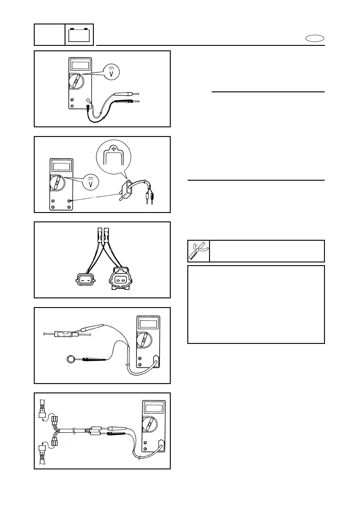
ELECTRICAL ANALYSIS
● When measuring the peak voltage, con-
nect the peak voltage adaptor to the digi-
tal tester and switch the selector to the
DC voltage mode.
NOTE:
● Make sure the adaptor leads are properly
installed in the digital circuit tester.
● Make sure the positive pin (the “+” mark
facing up as shown) on the adaptor is
installed into the positive terminal of the
tester.
● The test harness is needed for the follow-
ing tests.
Å Voltage measurement
ı Peak-voltage measurement
Å
ı
Test harness (for the pulser coil and stator
coil)
Test harness:
YB-06768/90890-06768
Checking steps:
● Disconnect the original coupler con-
nections.
● Connect the test harness between the
original couplers.
● Connect the digital tester terminals to
the terminals which are being checked.
● Start or crank the engine and observe
the measurement.
 Loading...