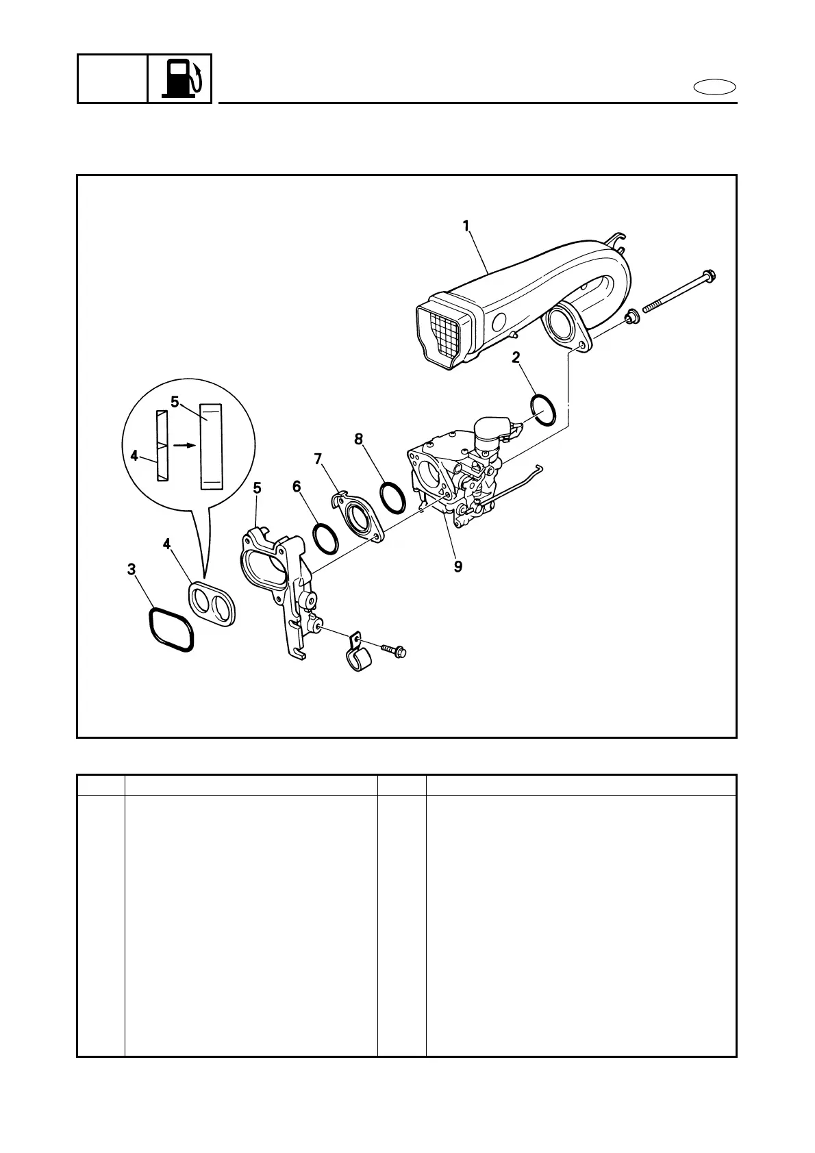
EasyManuals Logo

Yamaha F25A Service Manual

Yamaha F25A
444 pages
To Next Page IconTo Next Page
To Previous Page IconTo Previous Page
Page #98 background imageLoading...
Page #98 background image
4-4
E
FUEL
CARBURETOR UNIT
EXPLODED DIAGRAM
REMOVAL AND INSTALLATION CHART
Step Procedure/Part name Q’ty Service points
CARBURETOR UNIT DISASSEM-
BLY
Follow the left “Step” for removal.
1 U-shaped air funnel 1
2 O-ring 1 39.3
×
2.6 mm
3 O-ring 1 50.4
×
3.5 mm
4 Intake flow separator 1
5 Intake manifold bracket 1
6 O-ring 1 34.6
×
2.6 mm
7 Spacer 1
8 O-ring 1 34.6
×
2.6 mm
9 Carburetor 1
Reverse the disassembly steps for instal-
lation.

Table of Contents

Other manuals for Yamaha F25A

Questions and Answers:

Question and Answer IconNeed help?

Do you have a question about the Yamaha F25A and is the answer not in the manual?

Yamaha F25A Specifications

General IconGeneral
BrandYamaha
ModelF25A
CategoryOutboard Motor
LanguageEnglish

Related product manuals