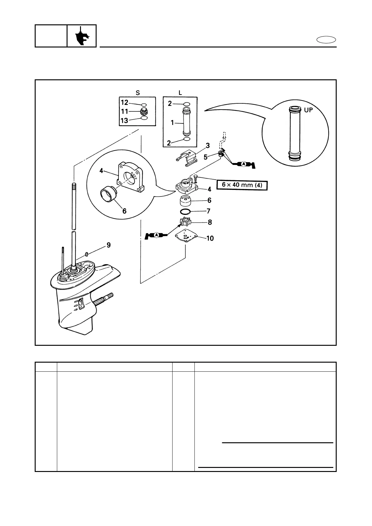
EasyManuals Logo

Yamaha F25A Service Manual

Yamaha F25A
444 pages
To Next Page IconTo Next Page
To Previous Page IconTo Previous Page
Page #210 background imageLoading...
Page #210 background image
6-3
E
LOWR
WATER PUMP
WATER PUMP
EXPLODED DIAGRAM
REMOVAL AND INSTALLATION CHART
Step Procedure/Part name Q’ty Service points
WATER PUMP REMOVAL
Follow the left “Step” for removal.
Lower unit Refer to “LOWER UNIT”.
1 Water tube 1
2 O-ring 2 25.8
×
2.4 mm
3 Impeller housing extension plate 1
4 Impeller housing 1
5 Water seal 1
6 Impeller housing cup 1
NOTE:
To install the impeller housing cup, turn
the drive shaft clockwise.

Table of Contents

Other manuals for Yamaha F25A

Questions and Answers:

Question and Answer IconNeed help?

Do you have a question about the Yamaha F25A and is the answer not in the manual?

Yamaha F25A Specifications

General IconGeneral
BrandYamaha
ModelF25A
CategoryOutboard Motor
LanguageEnglish

Related product manuals