5-39
POWR
E
CRANKCASE, CRANKSHAFT ASSY., AND
CYLINDER BODY
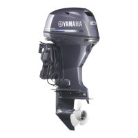
● Put a piece of Plastigauge
on each
main journal.
● Install the other half of the bearings 1
into the crankcase.
● Install the crankcase onto the cylinder
body.
● Tighten the bolts in the proper
sequence and in two stages.
T
R
.
.
Bolt (M8):
1st: 15.0 Nm
(1.5 m • kg, 11.1 ft • lb)
2nd: 30.0 Nm
(3.1 m • kg, 22.1 ft • lb)
Bolt (M6):
1st: 6.0 Nm
(0.6 m • kg, 4.4 ft • lb)
2nd: 12.0 Nm
(1.2 m • kg, 8.9 ft • lb)
● Remove the crankcase.
● Measure the width of the compressed
Plastigauge
on each main journal.
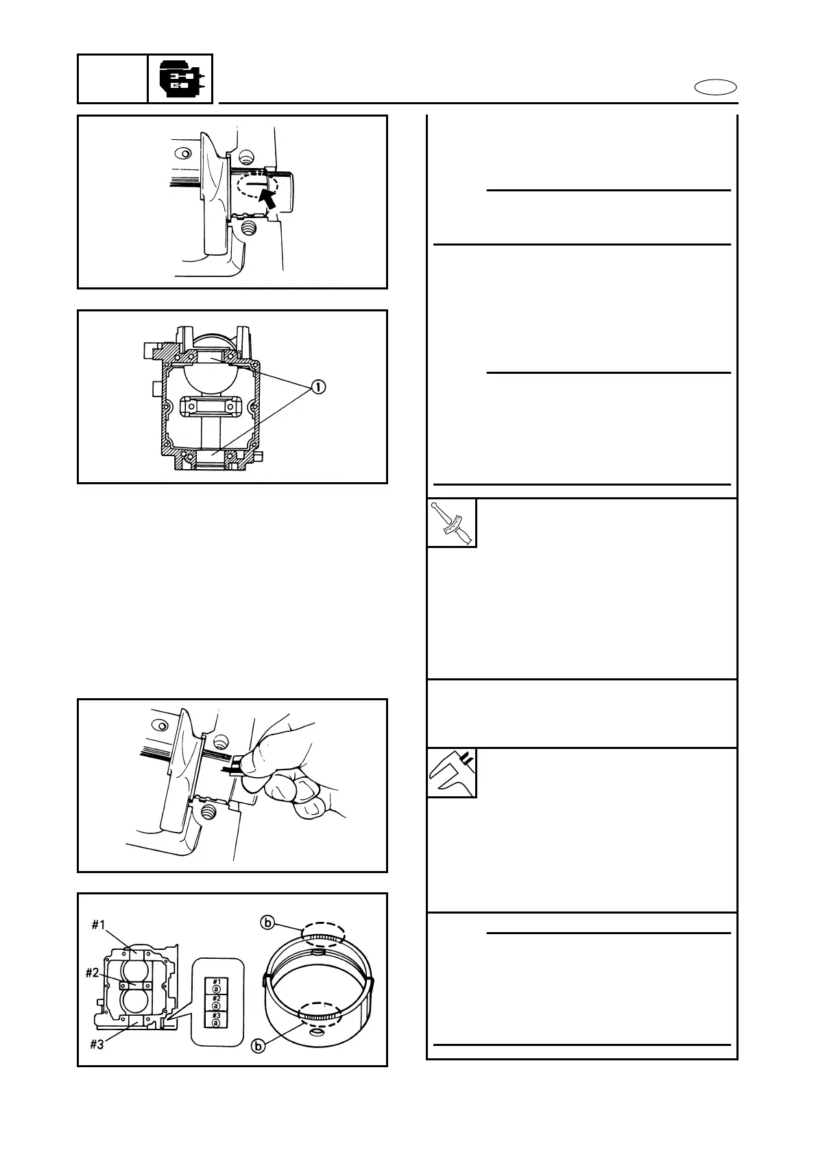
Crankcase main journal color
code indicator a:
A: Blue
B: Black
C: Brown
Bearing color code b:
A: Blue
B: Black
C: Brown
NOTE:
Do not put the Plastigauge
over the oil
hole in the main journal of the crankshaft.
NOTE:
● Align each bearing projection with the
notch in the crankcase.
● Do not move the crankshaft until the
main-bearing oil clearance measure-
ment has been completed.
NOTE:
● The crankcase color code indicator is
marked on the cylinder body as shown.
● Use the same bearing color as the color
which is indicated on the crankcase
(e.g., A(Blue) → Blue, etc.).

 Loading...