5-41
POWR
E
CRANKCASE, CRANKSHAFT ASSY., AND CYLINDER
BODY
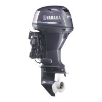
Connecting rod color code
indicator a:
A: Blue
B: Black
C: Brown
Bearing color code b:
A: Blue
B: Black
C: Brown
NOTE:
● Make sure the “Y” mark on the connect-
ing rod faces towards the flywheel side
of the crankshaft.
● Do not move the crankshaft until the
big-end oil clearance measurement has
been completed.
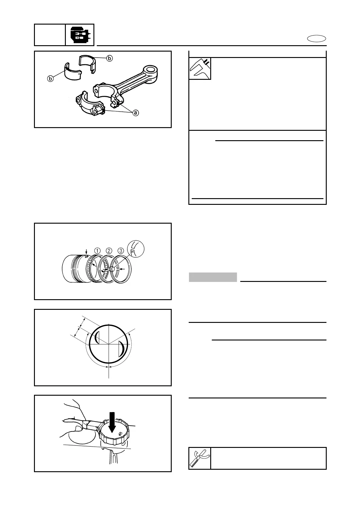
Piston ring installation
1. Install:
● Oil ring 1
● 2nd piston ring 2
● Top piston ring 3
CAUTION:
● Do not scratch the piston or break the pis-
ton rings.
● After installing the piston rings, check
that they move smoothly.
NOTE:
● Offset the piston-ring end gaps as shown.
a Oil ring side rail
b Oil ring expander
c 2nd piston ring
d Top piston ring
● Piston rings should be replaced as a set.
Å 20 ± 5 mm (0.79 ± 0.2 in) ı 120˚ ± 15˚
Piston installation
1. Install:
● Piston
Piston slider:
YU-33294/90890-06529
a
c
d
a
b
Å
ıı
Å
UP

 Loading...