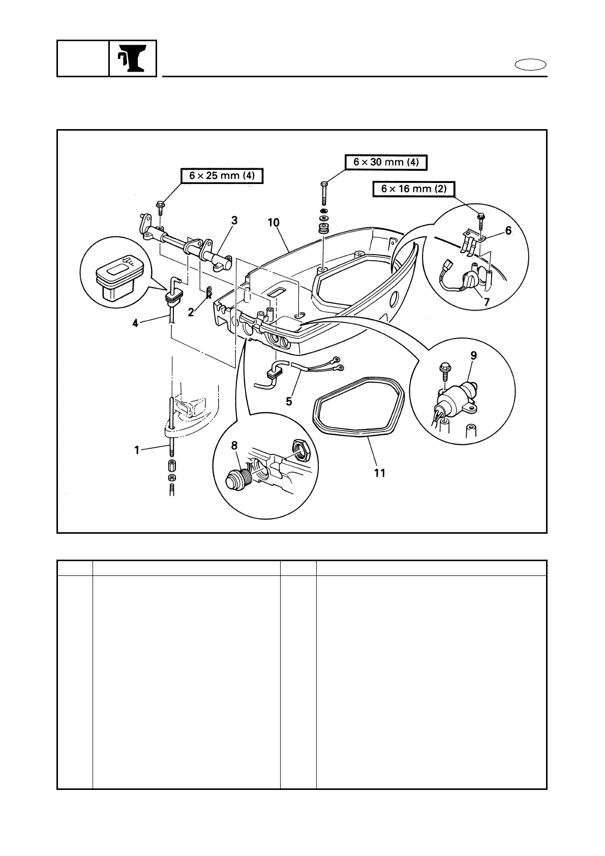
EasyManuals Logo

Yamaha F25A Service Manual

Yamaha F25A
444 pages
To Next Page IconTo Next Page
To Previous Page IconTo Previous Page
Page #290 background imageLoading...
Page #290 background image
7-6
E
BRKT
BOTTOM COWLING
BOTTOM COWLING
EXPLODED DIAGRAM
REMOVAL AND INSTALLATION CHART
Step Procedure/Part name Q’ty Service points
BOTTOM COWLING REMOVAL
Follow the left “Step” for removal.
Power unit Refer to “POWER UNIT” in chapter 5.
1 Shift rod 1
2 Clip 1
3 Shift rod lever 1
4 Shift rod 1
5 PTT motor lead (EHT, ET) 1
6 Trailer switch retainer (EHT, ET) 1
7 Trailer switch (EHT, ET) 1
8 Starter switch (EH, EHT) 1
9 Neutral switch (EH, EHT) 1
10 Bottom cowling 1
11 Rubber seal 1
Reverse the removal steps for installation.

Table of Contents

Other manuals for Yamaha F25A

Questions and Answers:

Question and Answer IconNeed help?

Do you have a question about the Yamaha F25A and is the answer not in the manual?

Yamaha F25A Specifications

General IconGeneral
BrandYamaha
ModelF25A
CategoryOutboard Motor
LanguageEnglish

Related product manuals