EasyManua.ls Logo

Yamaha F25A Service Manual

Yamaha F25A
444 pages
To Next Page IconTo Next Page
To Previous Page IconTo Previous Page
Page #416 background imageLoading...
Page #416 background image
8-30
–+
ELEC
E
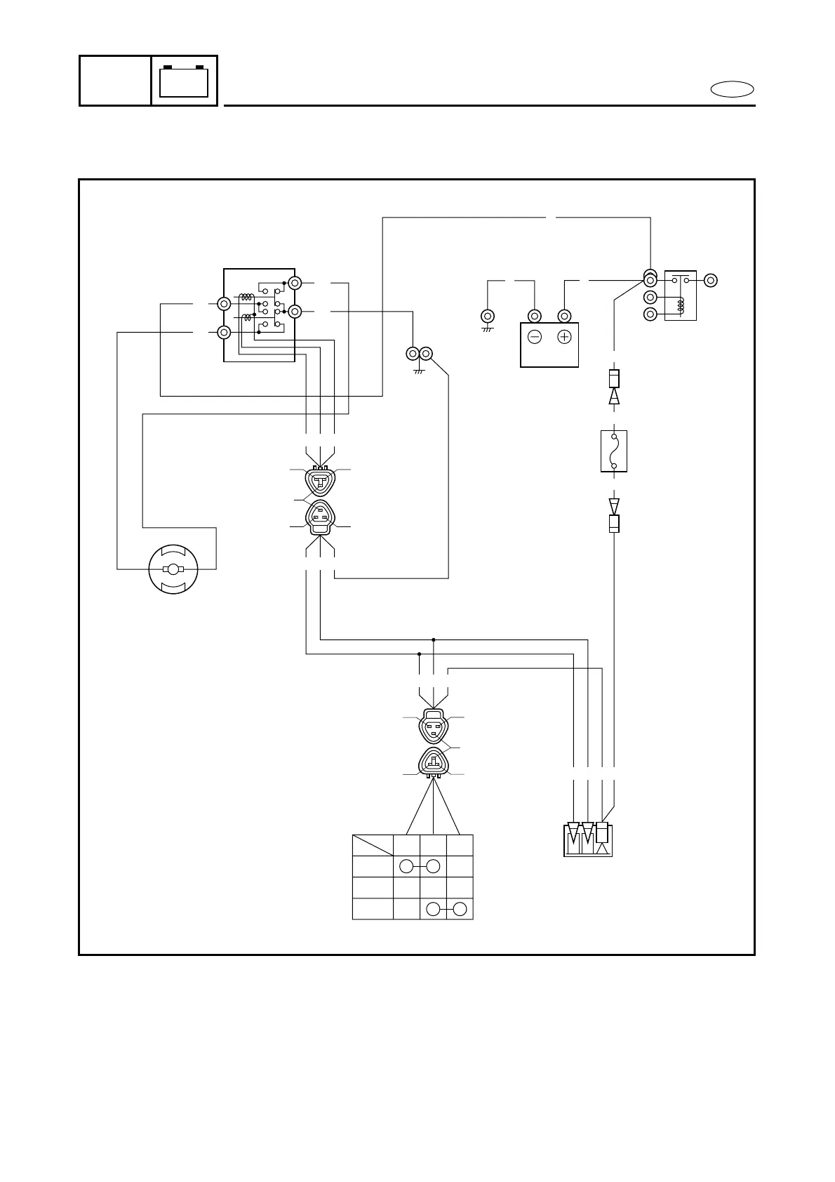
POWER TRIM AND TILT (PTT) CONTROL SYSTEM
POWER TRIM AND TILT (PTT) CONTROL SYSTEM (ET)
M
R
G
Lg Sb R
Lg Sb R R
Lg Sb B
Lg Sb B
L
B
R
R
R
B
R
1
2
3
5
4
R
UP
Sb R Lg
FREE
DOWN
Sb
Sb
Lg
B
Lg
Lg
Lg
Sb
Sb
R
1 Battery
2 Fuse
3 Trailer switch
4 Connector
5 PTT relay
6 PTT motor
B : Black
G : Green
L : Blue
Lg : Light green
R : Red
Sb : Sky blue

Table of Contents

Other manuals for Yamaha F25A

Questions and Answers:

Yamaha F25A Specifications

General IconGeneral
BrandYamaha
ModelF25A
CategoryOutboard Motor
LanguageEnglish

Summary

SAFETY WHILE WORKING

FIRE PREVENTION

Guidelines for safely handling flammable gasoline and preventing fires.

VENTILATION

Importance of proper ventilation for hazardous petroleum vapors and exhaust gases.

CHAPTER 2 SPECIFICATIONS

GENERAL SPECIFICATIONS

Overall specifications including dimensions, weight, performance, and power unit details.

MAINTENANCE SPECIFICATIONS

Specific maintenance data for engine, lower unit, and electrical systems.

TIGHTENING TORQUES

Torque specifications for various parts and assemblies.

CHAPTER 3 PERIODIC INSPECTION AND ADJUSTMENT

MAINTENANCE INTERVAL CHART

Provides a schedule for routine maintenance tasks based on operating hours and time intervals.

CHAPTER 5 POWER UNIT

CYLINDER HEAD AND OIL PUMP

Exploded view and removal/installation chart for cylinder head and oil pump components.

OIL PUMP

Exploded diagram, removal/installation chart, and service points for the oil pump.

CHAPTER 6 LOWER UNIT

LOWER UNIT

General information and procedures for the lower unit.

FORWARD GEAR AND DRIVE SHAFT

Exploded diagram, removal/installation, and service points for forward gear and drive shaft.

CHAPTER 7 BRACKET UNIT

POWER TRIM AND TILT (PTT) UNIT

Exploded view and removal/installation procedures for the power trim and tilt unit.

CHAPTER 8 ELECTRICAL SYSTEM

ELECTRICAL ANALYSIS

Inspection procedures using digital circuit testers, peak voltage measurement, and test harnesses.

IGNITION SYSTEM

Details on ignition spark gap, peak voltage, spark plugs, and engine stop switch.

IGNITION CONTROL SYSTEM

Information on pulser coil, oil pressure switch, engine temperature sensor, and warning lamp.

CHAPTER 9 TROUBLE-ANALYSIS

TROUBLE-ANALYSIS

Guide to identifying and diagnosing engine problems and their common causes.

TROUBLE-ANALYSIS

ENGINE WILL NOT START

Troubleshooting steps when the engine fails to start.

ROUGH IDLING

Troubleshooting steps for rough or unstable engine idling.

ENGINE STALLS

Troubleshooting steps when the engine stops unexpectedly.

ENGINE WILL NOT STOP

Troubleshooting steps when the engine does not shut off.

POOR PERFORMANCE

Troubleshooting steps for reduced engine performance or power.

OVERHEATING

Troubleshooting steps for engine overheating issues.

Related product manuals