316 ZXP Series 7 Card Printer Service Manual P1036102-007
Replacement Procedures for the High-Capacity Output Hopper
Procedures: Sensors
Sensors
Prior to starting this procedure, the left side panel must be removed. See
“Left Side Panel” on page 304 for details.
While these procedures can be done without removing the drive assembly and
PCBA, it is recommended that the aforementioned components be removed to avoid
damaging the PCBA with any tools while trying to disconnect or connect the sensors.
Hopper Present Sensor
Removal
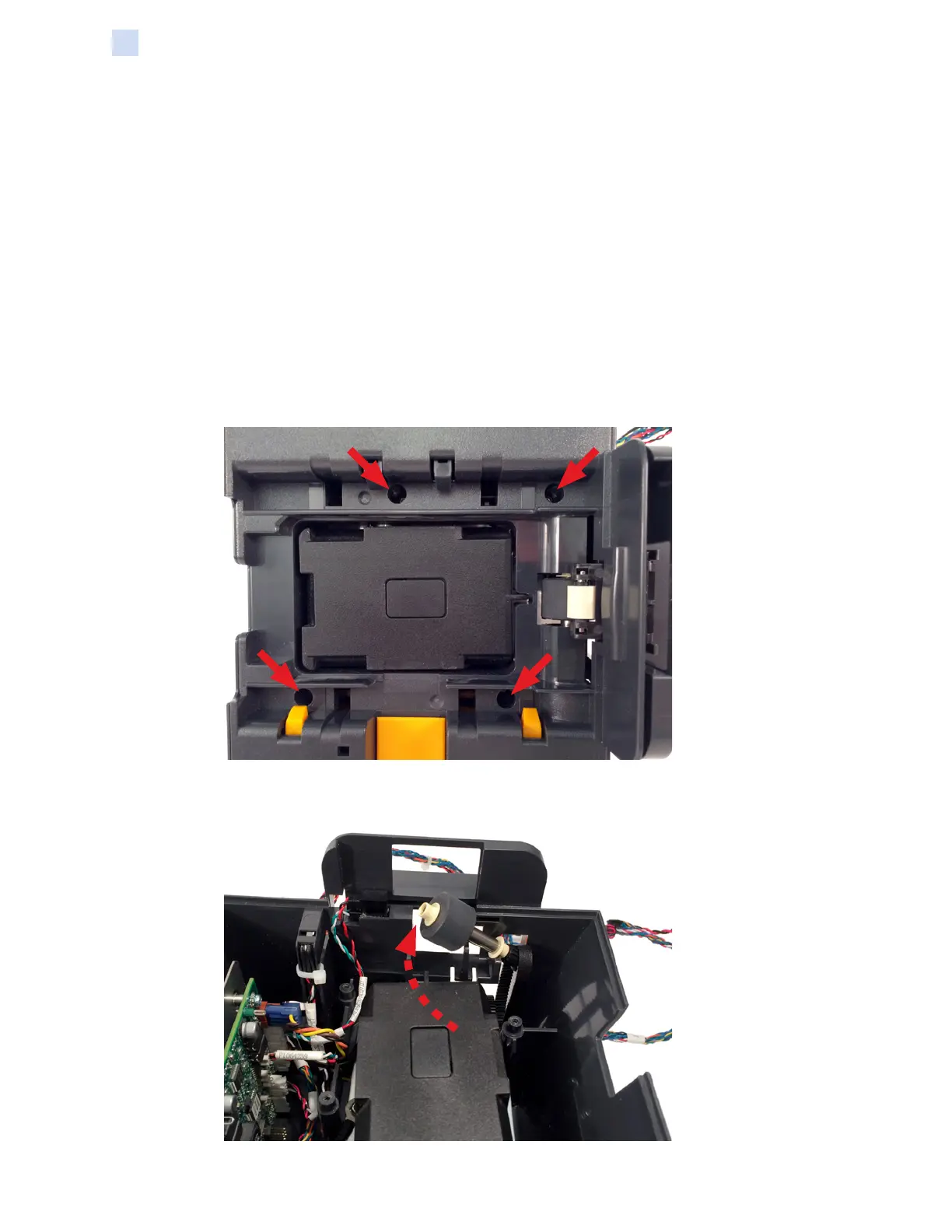
Step 1. Remove the four (4) screws securing the base cover and latch assembly to
the stacker assembly.
Step 2. Remove the platen roller and drive belt.
 Loading...
