P1036102-007 ZXP Series 7 Card Printer Service Manual 347
Replacement Procedures for the High-Capacity Output Hopper
Procedures: Base Housing
Base Housing
Prior to starting this procedure, the left side panel must be removed. See
“Left Side Panel” on page 304 for details.
This procedure covers procedures for replacement of the base housing, as well as the
stacker entry sensor which is UV glued to the base housing at the factory.
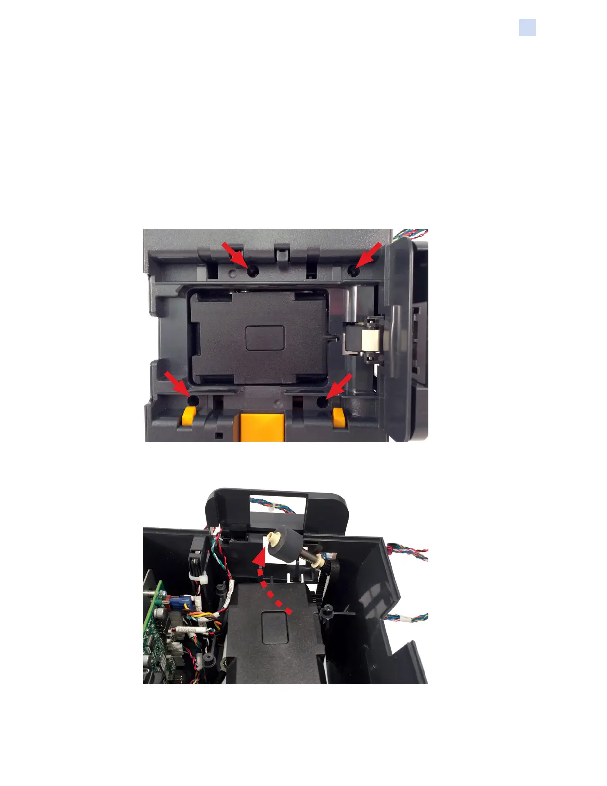
Removal
Step 1. Remove the four (4) screws securing the base cover and latch assembly to
the stacker assembly.
Step 2. Remove the platen roller and drive belt.
 Loading...
