Mains filters 167
Installation guidelines
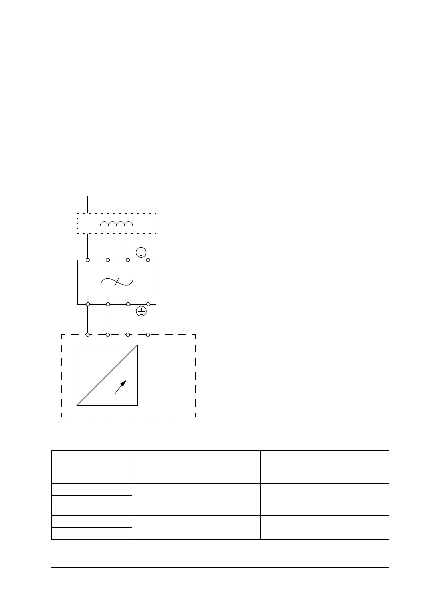
• If a mains choke is also installed, the mains filter is connected between the mains
choke and the drive. See the diagram below.
• For optimal operation of the filter, the drive and the filter must be mounted on the
same conductive surface.
• Ensure the filter does not block the airflow through the drive.
• Keep the cable between the drive and the filter as short as possible.
Connection diagram
~
AC supply
MicroFlex e190
Mains choke (if present)
Mains filter
~
L1 L2 L3
L1’ L2’
L1 L2 L3
PE
PE
L3’
L1 L2 L3
Selection table
230VAC 1Ø
Meets EN 61800-3, category C2
with
motor cable <50m
230VAC 3Ø
Meets EN 61800-3, category C2
with
motor cable <50m
The mains filters are protected to IP20.
Drive type
MFE190-04xx...
-01A6-2 OFI-02
or
OFI-01
OFI-03
-03A0-2
-06A0-2
OFI-01
JFI-02
-09A0-2
 Loading...