78 Electrical installation: input / output
Serial interfaces & SinCos
The MicroFlex e190 supports the following feedback types, for use with linear and
rotary motors:
• EnDat 2.1
• SinCos encoders (1 V pk-pk, 2.5 V reference)
• BiSS-B (Bi-directional Synchronous Serial In
terface), SSI (Synchronous Serial
Interface) or EnDat 2.2
• Smart Abs absolute encoders
• Hiperface
Twisted pairs must be used for each compl
ementary signal pair e.g. CHA+ and CHA-
or Data+ and Data-. Maximum cable length is 30 m.
The overall cable shield (screen) must be conn
ected to the metallic shell of the D-
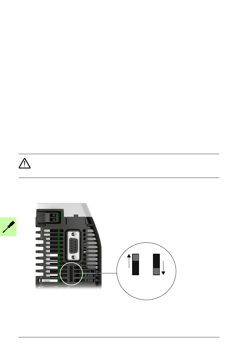
type connector. The encoder supply on pin 12 provides either 5.5 V or 8-12 V to the
encoder, selected using the switch behind connector X7 (500 mA maximum, less if
ot
her encoder outputs are in use; see page 76).
WARNING! Check the feedback device’s power input specifications before
using the 8 V position. Selecting the wrong voltage could damage your
feedback device.Typically 8 V is only used when using an Hiperface encoder.
 Loading...