30 Operation principle and hardware description
Main circuit
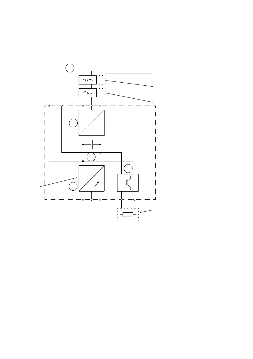
The diagram below shows the main circuit of the drive. For further information on the
power unit, see the chapter Electrical installation: AC input / DC input, motor and
brake.
~
=
Motor output
+–
R+/UDC+ UDC- L2 L3L1
~
=
VWU R- R+/UDC+
AC supply
MicroFlex e190
Inverter
Mains choke (optional)
Mains filter
RGJxxx braking resistor
(optional)
3
2
4
5
1-phase or 3-phase supply
1
1. AC supply. 1-phase 200...240 V or 3-phase 200...240 V phase-to-phase (±10%).
2. Rectifier. Converts alternating current and
voltage to direct current and voltage.
3. DC link. DC circuit between rectifier and inverter.
4. Inverter. Converts direct current and voltage to alternating current and voltage.
5. Brake chopper. Conducts the surplus energy from the intermediate DC circuit of
th
e drive to the brake resistor when necessary. The chopper operates when the
DC link voltage exceeds a certain maximum limit. The voltage rise is typically
caused by deceleration (braking) of a high inertia motor. The user must obtain and
install a brake resistor when needed.
 Loading...