74 Electrical installation: input / output
Ethernet ports
E1 / E2: Real-time Ethernet port
The E1 and E2 Ethernet ports on the top panel of the MicroFlex e190 are used for
real-time Ethernet fieldbus connections such as EtherCAT® and Ethernet
POWERLINK®. For full details about the fieldbus connections, see the Mint
WorkBench help file.
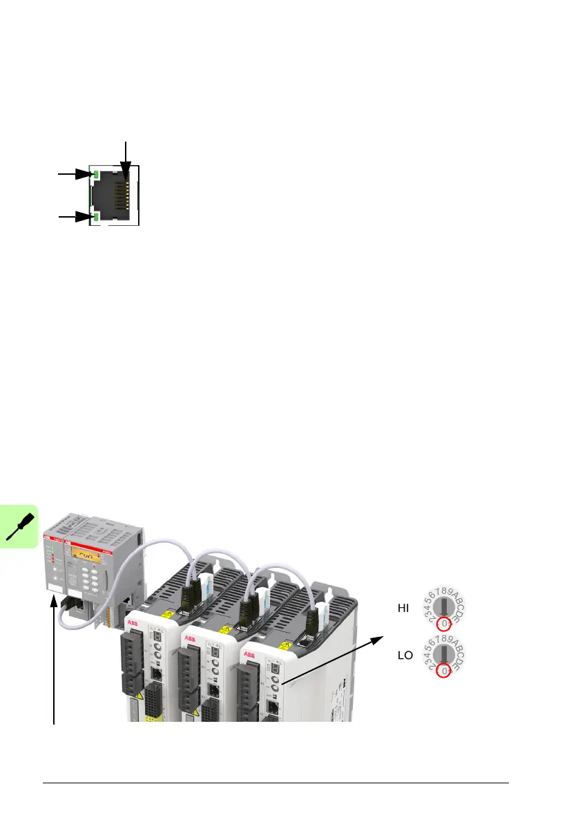
In an EtherCAT network the E2 (IN) port must be
connected to the master side of the
network. The E1 (OUT) port, if used, must be connected to the IN port of the next
slave device in the network. Set both front panel rotary HI / LO switches to 0 to select
EtherCAT slave mode.
In an Ethernet POWERLINK network the connectors are identical.
See MicroFlex e190 indicators on page 111 for a description of the fieldbus status
indicators.
EtherCAT connections:
1
2
3
4
5
6
7
8
TX+
TX-
RX+
(NC)
(NC)
RX-
(NC)
(NC)
 Loading...