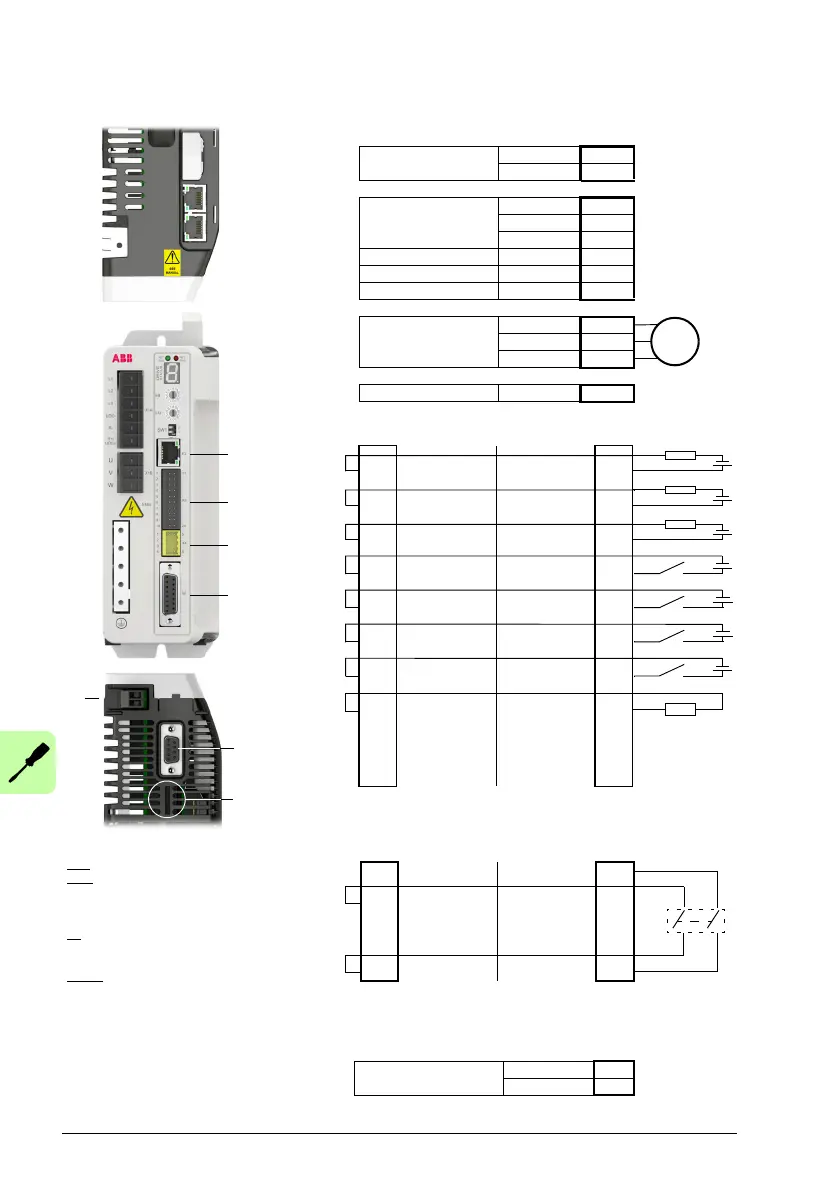
Wire sizes and tightening torques:
X1A: Dinkle EC762V-B3253206P-BK
X1B: Dinkle EC762V-B3253203P-BK
0.2...6.0 mm
2
(30*...10 AWG)
* Minimum size for UL installations is 14 AWG.
Torque: 0.7 N·m (6.2 lbf·in)
X2: Phoenix Contact MVSTBR 2,5HC/ 2-ST-5,08
0.2...2.5 mm
2
(24...12 AWG)
Torque: 0.6 N·m (5.3 lbf·in)
X3, X4: Weidmüller B2L 3.50/20/180,
Weidmüller B2L 3.50/8/180
0.2...1.0 mm
2
(28...16 AWG)
Notes:
The wiring shown is for demonstrative purposes
only. Complete information for all connectors,
including X7 and X8, is provided in this chapter
and the chapter Technical data.
E1/E2
Ethernet fieldbus IN E2
OUT E1
X1A
AC input
200...240 V AC ±10%
L1 1
L2 2
L3 3
DC bus- UDC- 4
Brake- R- 5
DC bus+ / Brake+ R+/UDC+ 6
X1B
Motor output
U1
V2
W3
E3
Ethernet host (PC) 1
X3 X3
1
Status-/DO0- Status-/DO0+
11
2DO2- DO2+12
3DO1- DO1+13
4 DI2- DI2+ 14
5 DI3- DI3+ 15
6 DI1- DI1+ 16
7 DI0- DI0+ 17
8 AGND AO0 18
9AI0- AI0+19
10 Shield Shield 20
E2
E1
X1A
X1B
E3
X3
X4
X8
X7
X2
Feedback voltage
selector
DO0-DO2: Maximum 100 mA per output, R
load
> 250 ohm.
AI0: Differential and single-ended connections are possible.
X4 X4
1
STO1 STO1
5
2STO2 STO26
3SGND SGND7
4 24 V out 24 V out 8
Safe Torque Off: Both circuits must be closed for the drive to start.
X2
(Optional) Control circuit
supply input: 24 V, 1 A
0 V 1
+24 V IN 2
M
 Loading...