Electrical installation: input / output 77
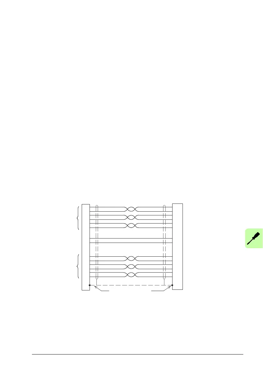
Twisted pairs must be used for each complementary signal pair e.g. CHA+ and CHA-
or Data+ and Data-.
The overall cable shield (screen) must be connected to the metallic shell of the D-
type connector.
In Mint WorkBench, the primary motor feedback
encoder on connector X8 is encoder
0. The extra incremental encoder input formed by digital inputs DI1 and DI2 is
encoder 1 (see page 66). The other extra incremental en
coder input on connector X7
is encoder 2 by default (see page 83), but alternatively connector X8 can be
configured as encoder input 2 (see page 81).
Incremental encoder with Halls
The incremental encoder connections (ABZ channels and Hall signals) are made
using the 15-pin D-type female connector X8. The encoder inputs (CHA, CHB and
CHZ) accept differential signals only. Twisted pairs must be used for each
complementary signal pair e.g. CHA+ and CHA-. The Hall inputs may be used as
differential inputs (recommended for improved noise immunity) or single ended
inputs. When used as single ended inputs, leave the Hall U-, Hall V- and Hall W- pins
unconnected. The overall cable shield (screen) must be connected to the metallic
shell of the D-type connector. The encoder supply on pin 12 typically provides 5.5 V
to th
e encoder (500 mA maximum, less if other encoder inputs are in use; see page
76). Maximum cable length is 30 m.
X8
Connect overall
shield to connector
backshells
Twisted pairs
Motor
CHA+
CHA-
CHB+
CHB-
CHZ+ (INDEX)
CHZ- (INDEX)
Hall U+
Hall U-
Hall W+
Hall W-
Hall V+
Hall V-
+5.5 V out
DGND
Encoder
Feedback
Hall
Feedback
 Loading...