Electrical installation: input / output 81
Extra incremental encoder
Some applications require the connection of multiple encoders typically when:
• A single axis has multiple encoders on the same motion system to eliminate
mechanical errors (a dual encoder application).
• The drive is required to follow encoder signals given to it from a master encoder
input.
In both cases the drive can support a connection to an extra incremental encoder by
X7 (see page 83) or X8. The default extra incremental encoder input (encoder 2) is
X7.If X7 is occupied as an encoder output and the primary feedback type is one that
does not use the Hall/sin/cos inputs (Incremental encoder without Halls, BiSS-B, SSI,
EnDat 2.2, Smart Abs or resolver), the extra incremental encoder also can be
connected to X8.
Note: In Mint, this extra encoder input (encoder 2 on X8) is available only when
connector X7 has been configured as an encoder output (see page
84).
When connector X8 is specified as encode 2, a encoder breakout OPT-MF-200 need
to be mounted to split one 15-pin connector X8 into one 15-pin connectors X8A and
one 9-pin X8B. X8A is connected to motor feedback, while X8B is connected to an
extra incremental encoder (see page
180).
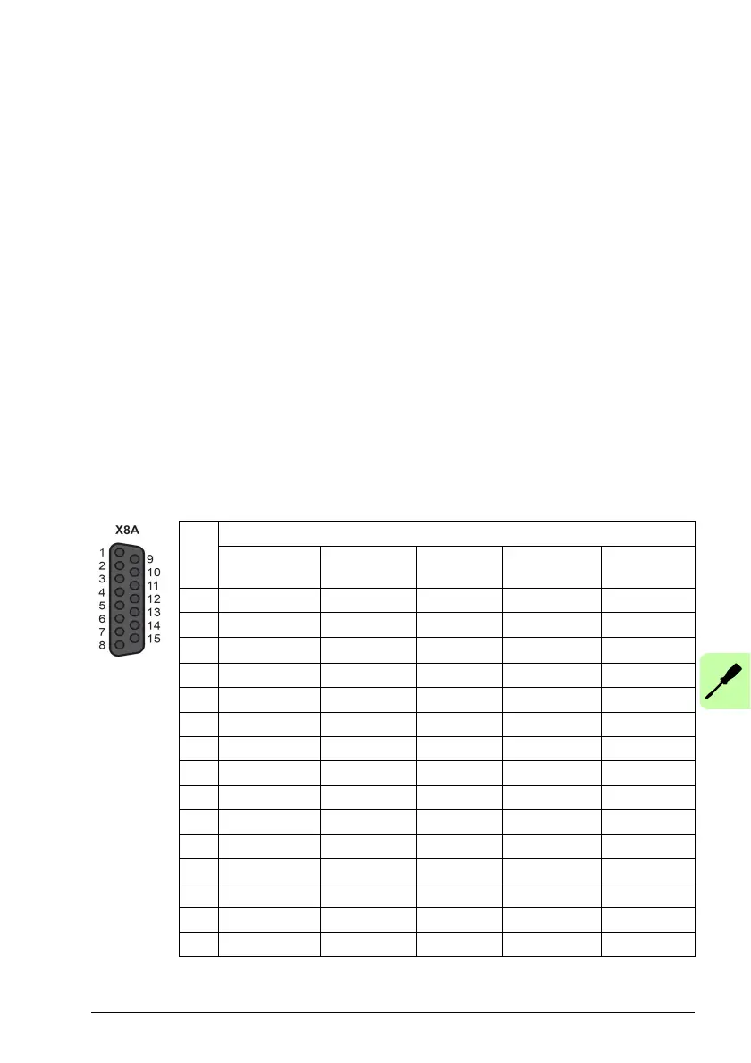
Pin X8A (Primary encoder)
Inc. encoder
without Halls
BiSS-B SSI EnDat 2.2 Smart Abs
1 CHA+ Data+ Data+ Data+ Data+
2 CHB+ Clock+ Clock+ Clock+ (NC)
3 CHZ+ (NC) (NC)
(NC)
(NC)
4 (NC) (NC) (NC) (NC) (NC)
5 (NC) (NC) (NC) (NC) (NC)
6 (NC) (NC) (NC) (NC) (NC)
7 (NC) (NC) (NC) (NC) (NC)
8 (NC) (NC) (NC) (NC) (NC)
9 CHA- Data- Data- Data- Data-
10 CHB- Clock- Clock- Clock- (NC)
11 CHZ- (NC) (NC) (NC) (NC)
12 +5.5 V out +5.5 V out +5.5 V out +5.5 V out +5.5 V out
13 DGND DGND DGND DGND DGND
14 (NC) (NC) (NC) (NC) (NC)
15 (NC) (NC) (NC) (NC) (NC)
 Loading...