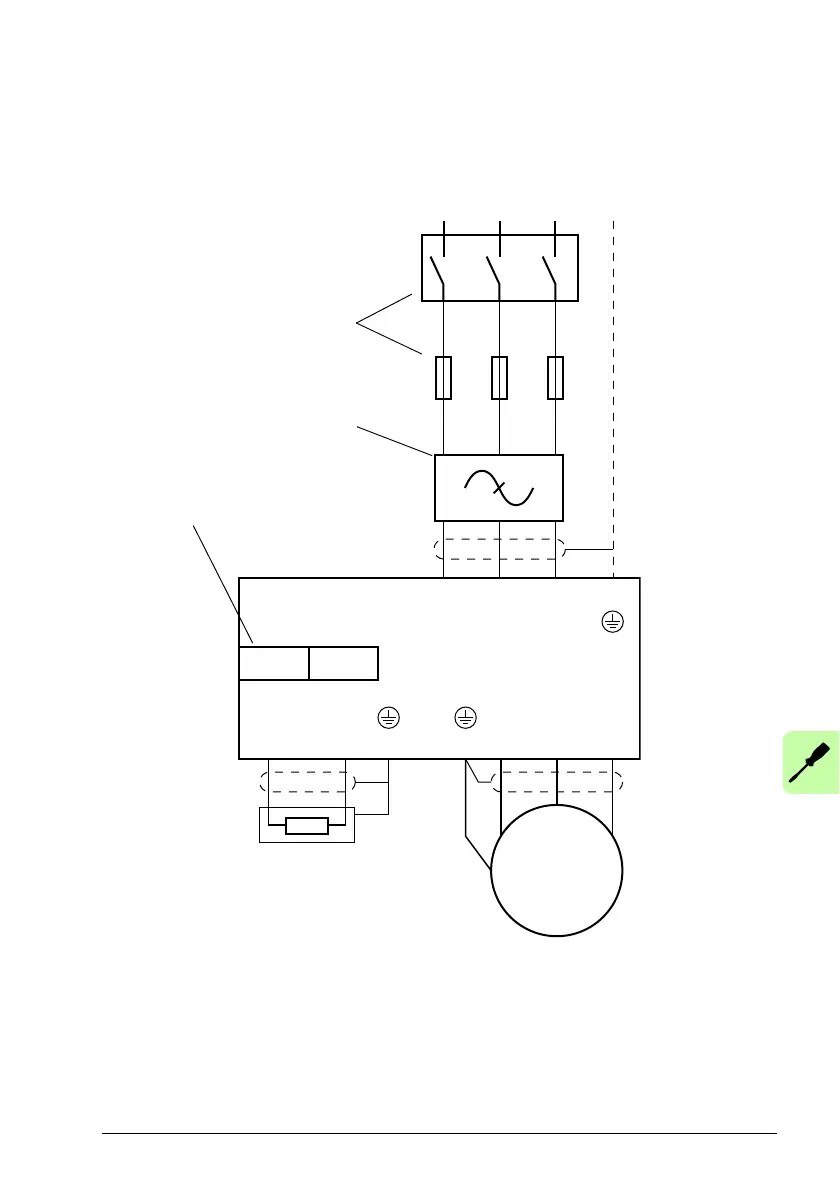
Optional braking
resistor (see the
chapter Resistor
braking on page 42)
Mains filter (optional). See the
chapter Mains filters (page 165).
Notes:
– If shielded supply (input) cable is used, and the conductivity of the shield is less than 50% of
the conductivity of a phase conductor, use a cable with a ground conductor or a separate PE
cable (1).
– For motor cabling, use a separate ground cable (2) if the conductivity of the cable shield is less
than 50% of the conductivity of a phase conductor and the cable has no symmetrical ground
conductors. See also section Selecting the power cables on page 45.
– AC supply (3), 1-phase 200...240 V (±10%) or 3-phase 200...240 V phase-to-phase (±10%).
L1 and L2 are used for single phase supply.
The UDC+/UDC- connectors can be
used for common DC configurations.
See page 54.
For alternatives, see Planning the
electrical installation: Supply
disconnecting device (page 42).
 Loading...