176 Resistor braking
Resistor derating
The brake resistors shown in the previous table can achieve their stated power rating
only when mounted on a heat sink. In free air a derating must be applied.
Furthermore, in ambient temperatures greater than 25 °C (77 °F), a temperature
d
erating must be applied.
Duty cycle
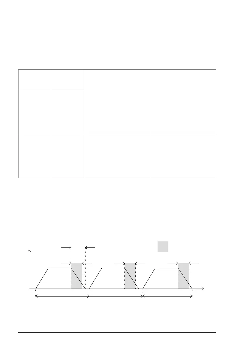
The braking duty cycle is the amount of time taken braking as a proportion of the
overall application cycle time. For example, the following diagram shows a system
which performs a trapezoidal move profile, with braking during part of the
deceleration phase. The braking duty is 0.2 (0.5 second braking / 2.5 second cycle
time):
t
v
Decel time
Braking active
2.5 s
(Cycle time)
2.5 s
(Cycle time)
2.5 s
(Cycle time)
0.5 s 0.5 s 0.5 s
Resistor part
number
Nominal
power rating
(W)
In free air On heat sink
RGJ139
RGJ160
100 Derate power linearly from:
80% @ 25 °C (77 °F)
to
70% @ 55 °C (113 °F)
Derate power linearly from:
100% @ 25 °C (77 °F)
to
88% @ 55 °C (113 °F)
Typical heat sink:
200 mm x 200 mm x 3 mm
RGJ260
RGJ360
200
300
Derate power linearly from:
70% @ 25 °C (77 °F)
to
62% @ 55 °C (113 °F)
Derate power linearly from:
100% @ 25 °C (77 °F)
to
88% @ 55 °C (113 °F)
Typical heat sink:
400 mm x 400 mm x 3 mm
 Loading...