50 Electrical installation: AC input / DC input, motor and brake
Checking the insulation of the assembly
Drive
Do not make any voltage tolerance or insulation resistance tests (e.g. hi-pot or
megger) on any part of the drive as testing can damage the drive. Every drive has
been tested for insulation between the main circuit and the chassis at the factory.
Also, there are voltage-limiting circuits inside the drive which cut down the testing
voltage automatically.
Supply cable
Check the insulation of the supply (input) cable according to local regulations before
connecting to the drive.
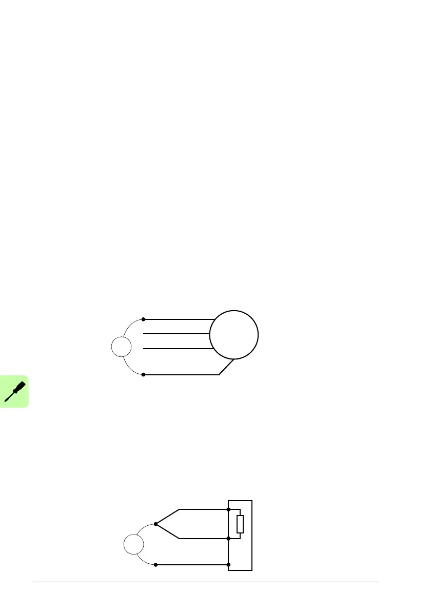
Motor and motor cable
Check the insulation of the motor and motor cable as follows:
• Check that the motor cable is connected to the motor
, and disconnected from the
drive output terminals U, V and W.
• Measure the insulation resistance between each phase and the motor PE
conductor by using a measuring voltage of 1 kV DC. The insulation resistance
must be higher than 1 Mohm.
Braking resistor assembly
Check the insulation of the braking resistor assembly (if present) as follows:
1. Check that the resistor cable is connected
to the resistor, and disconnected from
the drive output terminals R- and R+.
2. At the drive end, connect the R- and R+ co
nductors of the resistor cable together.
Measure the insulation resistance between the combined conductors and the PE
conductor by using a measuring voltage of 1 kV DC. The insulation resistance
must be higher than 1 Mohm.
 Loading...