Electrical installation: input / output 83
Incremental encoder input/output (X7)
The incremental encoder input/output connection provides A/B channels and a Z
index channel. Twisted pairs must be used for each complementary signal pair e.g.
CHA+ and CHA-. The Mint keyword ENCODEROUTCHANNEL is used to set the mode
of operation for X7. When set to the default value of -1, X7 operates as an input.
Input mode: ABZ incremental encoder (default)
By default, X7 is configured as an extra ABZ incremen
tal encoder input (encoder 2).
When operating as an encoder input, X7 can be used for a dual-loop feedback
system or connected to a master encoder for position following applications.
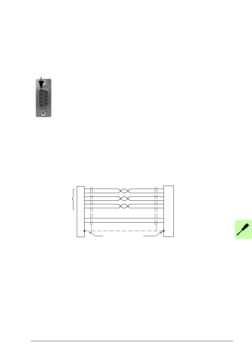
Incremental encoder cable connections:
X7
Connect overall
shield to connector
backshells
Twisted pairs
CHA+
CHA-
CHB+
CHB-
CHZ+ (INDEX)
CHZ- (INDEX)
+5.5 V out
DGND
Encoder
Feedback
Input mode: Step (pulse) and direction
Optionally, connector X7 can be configured as a step and direction input. Use one of
the follo
wing methods to select step and direction mode.
• In Mint WorkBench, choose the Parameters too
l and expand the Encoder family.
Click the EncoderMode entry, then click the value next to EncoderMode (Encoder
Channel 2). Check Bit 2: Step/Direction, then click OK. On the menu, choose
Tools, Store Drive Parameters.
• In Mint WorkBench, choose the Edit & Deb
ug tool. In the Command window enter
the command: ENCODERMODE(2)=4 (or other value where bit 2 is set). On the
menu, choose Tools, Store Drive Parameters.
1
2
3
4
5
CHA+
CHB+
CHZ+
(NC)
GND
6
7
8
9
CHA-
CHB-
CHZ-
+5.5 V out
 Loading...