INTRODUCTION
D - 1
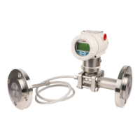
APPENDIX D - PTH PRESSURE TRANSMITTER
INTRODUCTION
This appendix covers the configuration and calibration functions of
the PTH Pressure Transmitter.
Refer to OPERATING PROCEDURES in Section 4 for information on
the following functions:
NOTE: To change calibration or configuration parameters of a smart
field device that is connected to an IMFBS01 module, the device
must be taken off-line. This is done at the INFI 90 OPEN console.
CREATE/MODIFY CONFIGURATION
A configuration can be created off-line, without a connected field
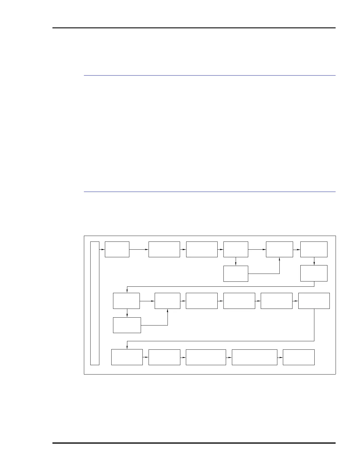
device. Refer to Figure D-1 for an overview of the configuration
function. The following table details the configuration process.
• Send configurations. • Select configurations.
• Get configurations. • Erase configurations.
• View configurations. • Operational functions.
Figure D-1. Configuration Flowchart (PTH)
T01341B
SELECT
DEVICE
TYPE
SELECT
MODE
SELECT
OUTPUT
TYPE
SELECT
OUTPUT
ACTION
ENTER
CONFIGURATION
ID TAG
ENTER
DAMPING
VALUE
ENTER
SECONDARY
UNITS
SELECT
ENGINEERING
UNITS
ENTER
LOWER/UPPER
SECONDARY VALUES
ENTER
LOWER/UPPER
TEMPERATURE ALARMS
ENTER
LOWER/UPPER
RANGE VALUES
SELECT
INITIALIZE
MODE
STORE
CONFIGURATION
SELECT
FAIL
MODE
SELECT
TRANSMITTER
TYPE
ENTER
CHANNEL
NUMBER
ENTER 5
INPUT/OUTPUT
POINTS
DIGITAL
FUNCTION
GENERATOR
HART ANALOG
OTHERS
C
O
N
F
I
G
U
R
E
ENTER
MESSAGE
TEXT
ENTER
DATE
ENTER
DESCRIPTOR
TEXT
 Loading...