INSTALLATION
SETUP AND PHYSICAL INSTALLATION
3 - 3
To install the clip leads cable:
1. Insert the female end of the clip leads cable connector into the
clip leads cable receptacle on the terminal with the button facing up
(Fig. 3-1). Make sure the connector is fully engaged.
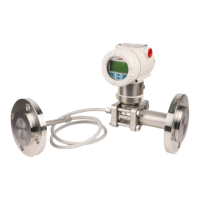
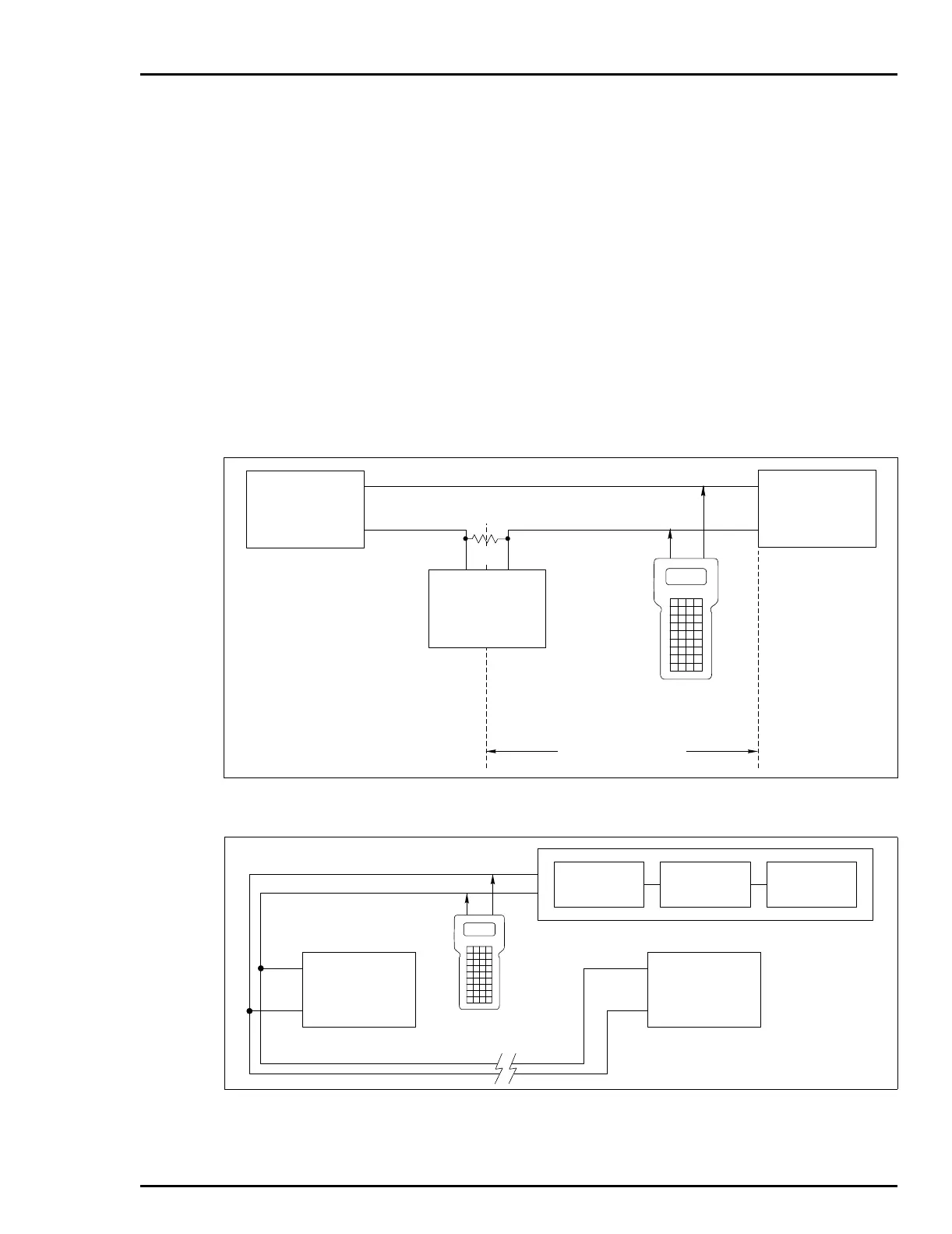
2. Connect the clip leads to the signal wires between the device and
the 250 ohm resistance. The clip leads connect across the signal
leads independent of signal direction or polarity. Refer to Figures 3-2
and 3-3.
To remove the clip leads cable:
1. Fully depress and hold in the button on the top of the clip leads
cable connector.
2. Firmly, but carefully pull the connector from the receptacle.
Figure 3-2. Analog Point-to-Point Wiring
Figure 3-3. Digital Field Bus and HART Wiring
T01323B
STT
+–
–
–
+
+
COMMUNICATIONS ARE
NOT POSSIBLE ON THIS
SIDE OF 250- RESISTOR
Ω
COMMUNICATIONS ARE
POSSIBLE ON THIS SIDE
OF 250- RESISTOR
Ω
SIGNAL WIRES
FIELD DEVICE
UP TO 1 MI. (1.6 KM)
SYSTEM POWER
SUPPLY
PWR/
OUTPUT
CONTROLLER,
RECORDER OR
CONTROL SYSTEM
250
Ω
T01324B
STT
SIGNAL WIRES
TERMINATION
UNIT
FIELD BUS
I/O MODULE
MFP/MFC
–
–
+
+
FIELD DEVICE 1
FIELD DEVICE 8
PWR/
OUTPUT
PWR/
OUTPUT
 Loading...