Geometries with no orientation support
Rockwell Automation Publication MOTION-UM002F-EN-P - February 2018 107
linear axis in the vertical direction. Use these guidelines when configuring a
SCARA Independent robot.
See also
Establish the reference frame for a SCARA Independent robot on page 107
Identify the work envelope for a SCARA Independent robot on page 109
Define configuration parameters for a SCARA Independent robot on page
109
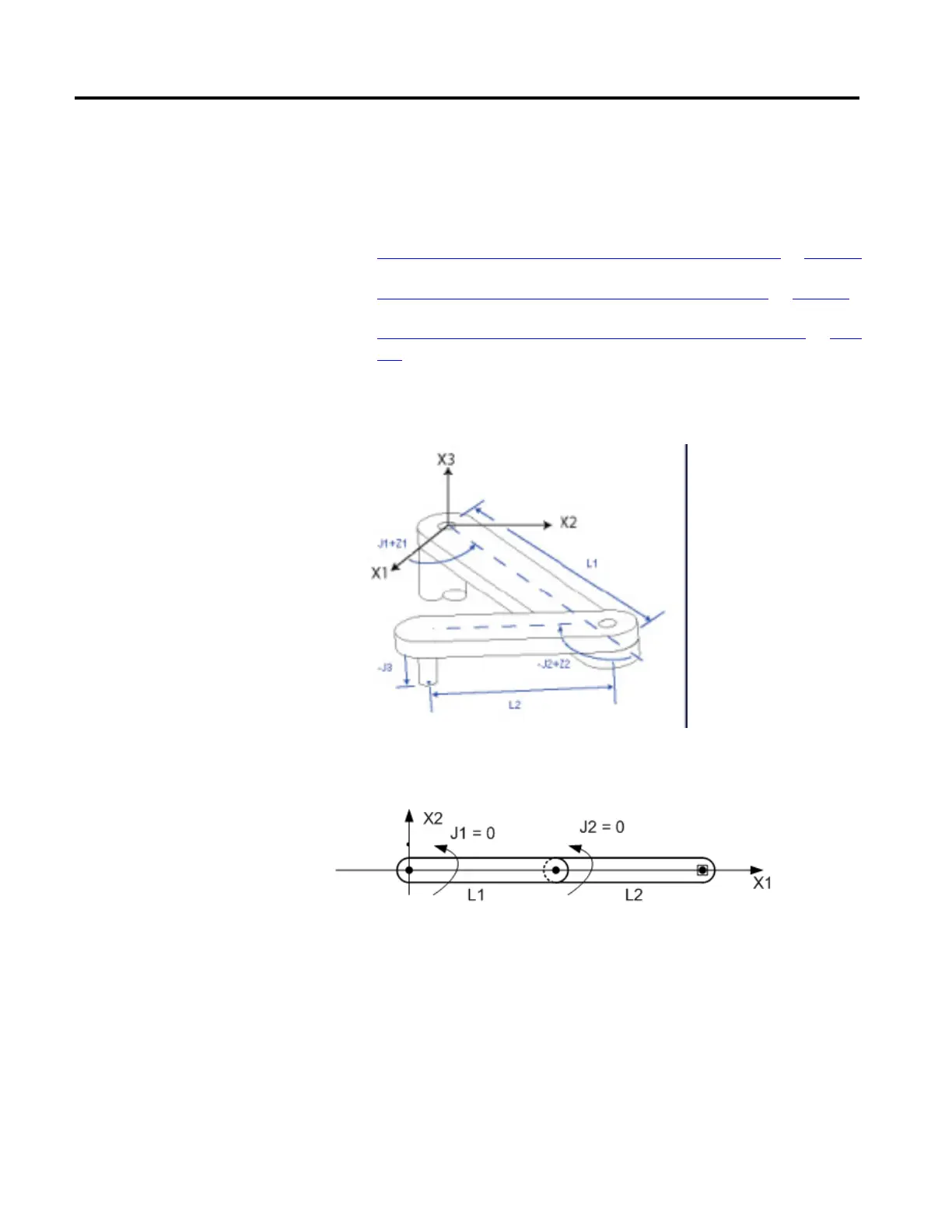
The reference frame for the SCARA Independent geometry is at the base of link
L1.
The internal kinematic equations are written as if the start position for the
SCARA Independent robot joints are as shown in this diagram.
• +J1 is measured counterclockwise around +X3 axis starting at an angle of J1
=0.0 when L1 is along the X1 axis.
• +J2 is measured counterclockwise starting with J2 = 0 when Link L2 is
aligned with link L1.
• +J3 is a prismatic axis that moves parallel to +X3 axis.
For information about alternate methods for establishing a reference frame, see
Articulated Independent robot.
Establish the reference frame
for a SCARA Independent robot
 Loading...

