Geometries with no orientation support
66 Rockwell Automation Publication MOTION-UM002F-EN-P - February 2018
Methods to establish a reference frame for Articulated Independent robot
on page 68
Work envelope for Articulated Independent robot on page 70
Define configuration parameters for Articulated Independent robot on
page 71
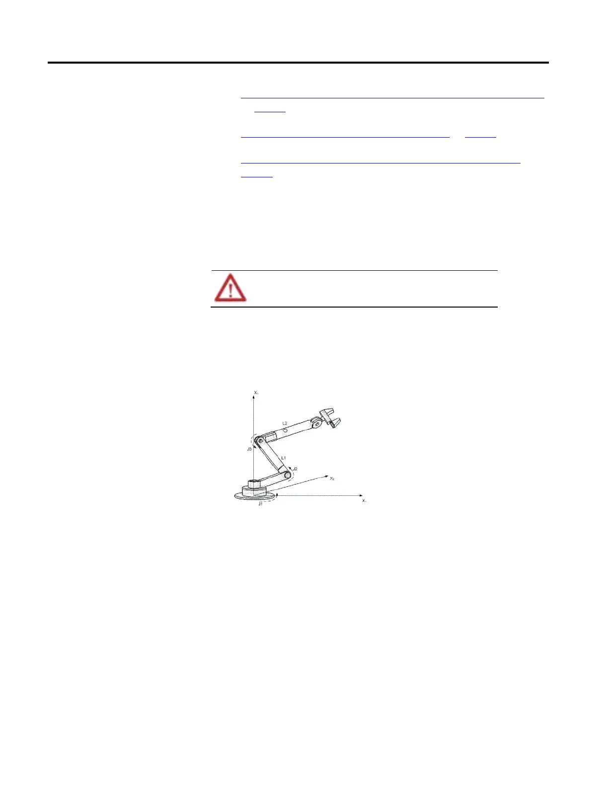
The reference frame is the Cartesian coordinate frame that defines the origin and
the three primary axes (X1, X2, and X3). These axes measure the real Cartesian
positions.
Failure to properly establish the correct reference frame for your robot can cause the
robotic arm to move to unexpected positions causing machine damage and/or injury or
death to personnel.
The reference frame for an Articulated Independent robot is located at the base of
the robot as shown in this figure.
Illustration 1
Before establishing the Joint-to-Cartesian reference frame relationship, it is
important to know some information about the Kinematic mathematical
equations used in the Logix controllers. The equations are written as if the
Articulated Independent robot joints are positioned as shown in the following
illustration.
Establish reference frame for an
articulated independent robot
 Loading...

