Geometries with orientation support
Rockwell Automation Publication MOTION-UM002F-EN-P - February 2018 145
End position from the Base Frame (P1):
(X = 0, Y = 0, Z = -800, Rx = 180
, Ry = 0, Rz = 0)
Tool Frame Offsets:
(Tx =50, Ty = 0, Tz = 150, TRx = 0, TRy = 0, TRz = -90
)
End position with Tool Frame (P2):
(X = 50, Y = 0, Z = -950, Rx = 180
, Ry = 0, Rz = 90 )
Refer to the manufacturer CAD drawings or datasheet to find relevant Tool
Offset values for the tool.
See also
Define coordinate system frames on page 134
Tool frame example on page 145
Work frame examples on page 139
Work frame offsets on page 137
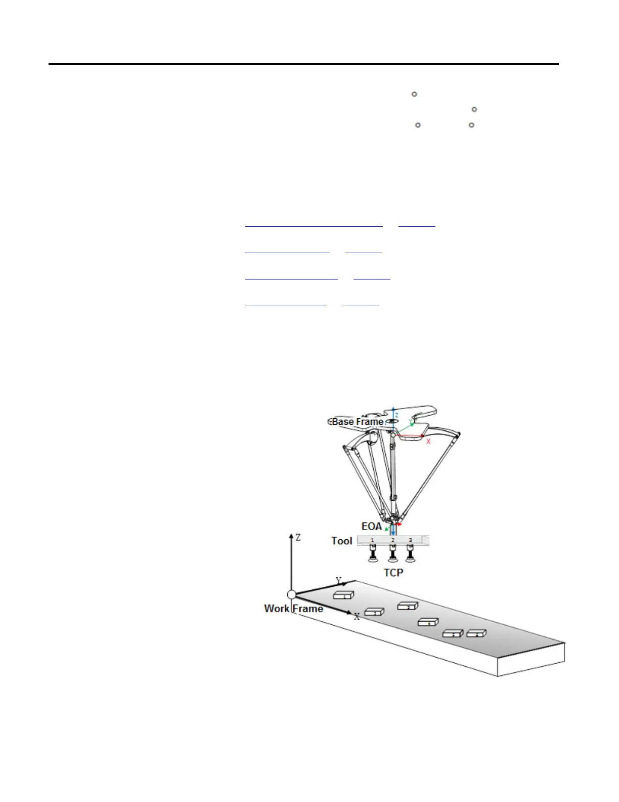
This illustration shows an example of using the Tool Frame in Pick & Place
applications. The custom tooling with three grippers (1, 2 and 3) is attached at the
end of 4-axis Delta robot. Each gripper is picking an object (1, 2, 3…6), placed at
different orientations from the moving conveyor and then putting them in to a
box with same orientations.
Each gripper is programmed as a separate tool and tool frames is associated with it.
All three TCP positions are measured using the tool offset values shown in the
 Loading...

