Geometries with no orientation support
Rockwell Automation Publication MOTION-UM002F-EN-P - February 2018 69
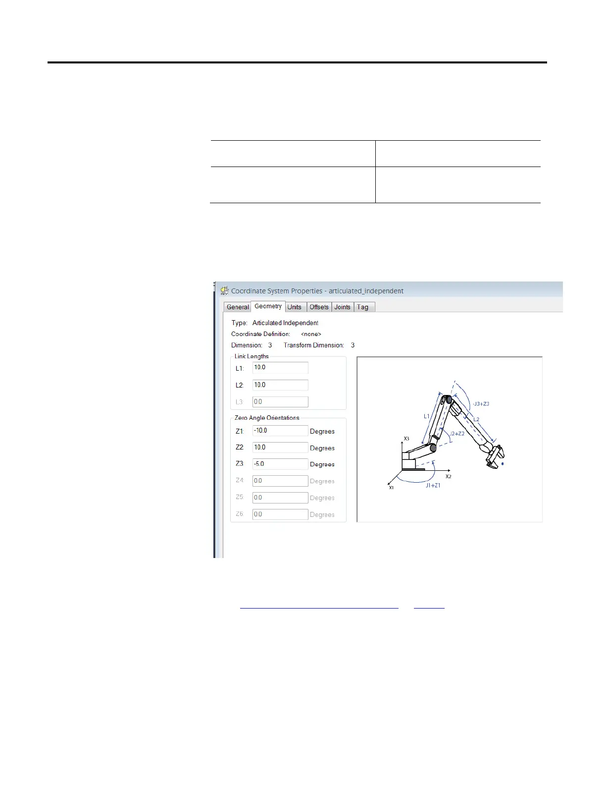
If the Actual Position tags do not show these values, configure the Zero Angle
Orientation parameters in the Coordinate System Properties dialog box for the
joint or joints that do not correspond.
If the Logix Designer application read-out values
are:
Set the Zero Angle Orientations on the Coordinate
System Properties dialog box to:
J1 = 10
J2 = 80
J3 = 5
Z1 = -10
Z2 = 10
Z3 = -5
The Joint-to-Cartesian reference frame relationship is automatically established by
the Logix controller after the Joint coordinate system parameters (link lengths,
base offsets, and end effector offsets) are configured and the MCT instruction is
enabled.
See also
Methods to establish a reference frame on page 68
Position the robot so that:
• L1 is parallel to the X3 axis.
• L2 is parallel to X1 axis.
Program a Motion Redefine Position (MRP) instruction for all three axes with the
following values:
Method 2 - Establish a reference
frame using a MRP instruction
 Loading...

