Geometries with orientation support
Rockwell Automation Publication MOTION-UM002F-EN-P - February 2018 195
Position X Y Z Rx Ry Rz
P2 200 200 200 180 0 30
P3 400 400 200 0 -90 -90
P4 400 400 100 0 -90 -90
P5 400 500 100 0 -90 90
Many robot geometries supported in ControlLogix integrated kinematics
transformations do not have enough degrees of freedom to support orientation
motion in the Ry axis, to include SCARA J1J2J3J6 and the Delta J1J2J3J6. Some
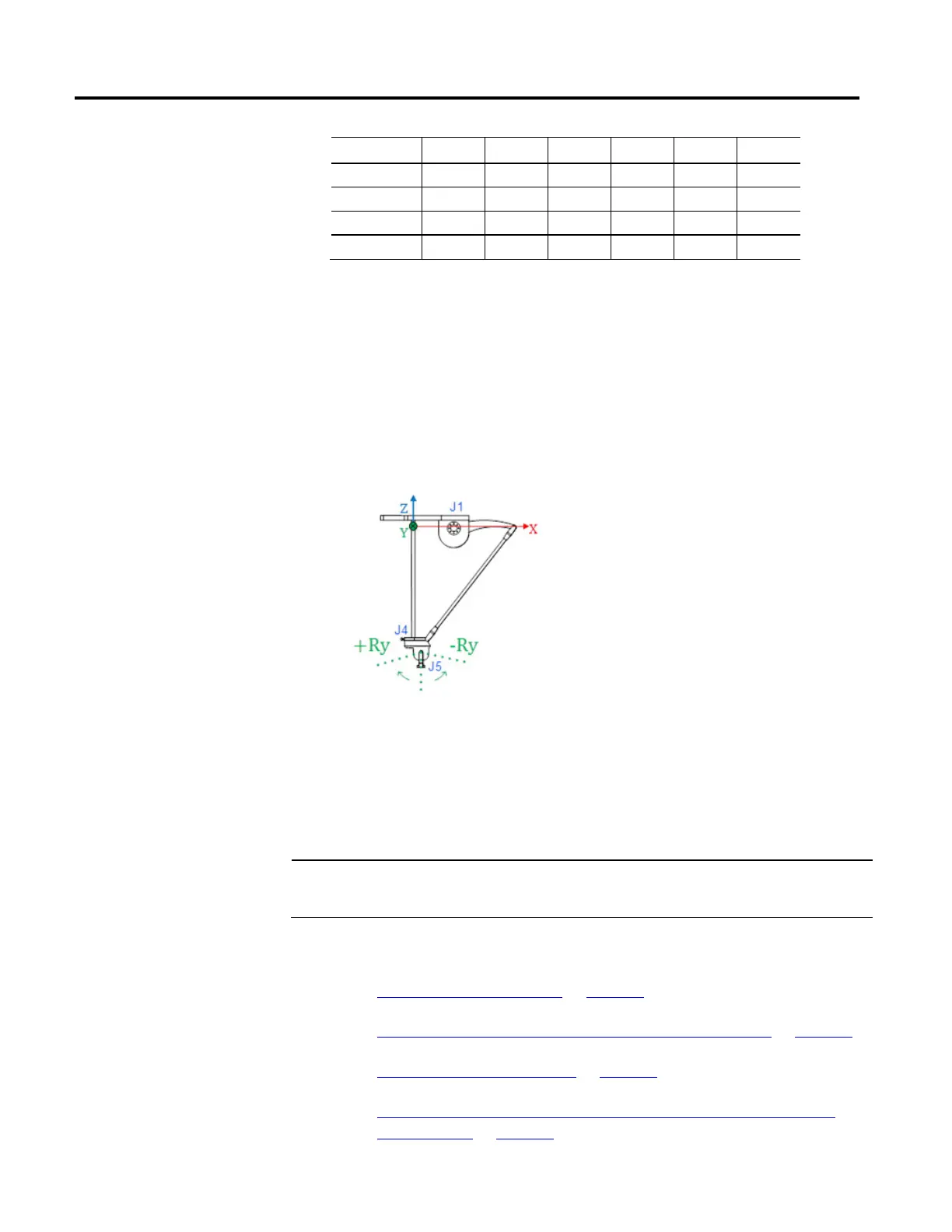
robot geometries, like the Delta J1J2J3J4J5, do support orientation moves in the
Ry axis. Systems like these allow for programmed motion on the Ry axis position,
which exhibits a mirror image orientation behavior. This introduces some notable
changes in how orientation moves of such systems are specified.
Tips:
Mirror image behavior occurs only when Motion Coordinated Transform with Orientation (MCTO)
transforms are active.
• The mirror image position data assumes no Tool or Work frame orientation offsets are applied.
• Ry orient
ation on the Delta J1J2J3J4J5 has opposite sign of J5 joint position. See Configuring the Delta
J1J2J3J4J5 Coordinate System for more details.
Important:
Avoid using the Motion Axis Move (MAM) instruction with orientation axes to prevent unintended motion on
the machine. It does not take into account the Euler angle rollover specifications or the Ry mirror orientation
effect when planning motion on these axes.
See also
Mirror image Ry orientation on page 196
Example of mirror image and flip behavior on Rx and Rz axes on page 198
Mirror orientation restrictions on page 198
Use MCPM to program Ry absolute moves for geometries with mirror
image position on page 199
orientation axis behavior
 Loading...

