Geometries with orientation support
Rockwell Automation Publication MOTION-UM002F-EN-P - February 2018 199
See also
Use MCPM to program Ry absolute moves for geometries with mirror
image position on page 199
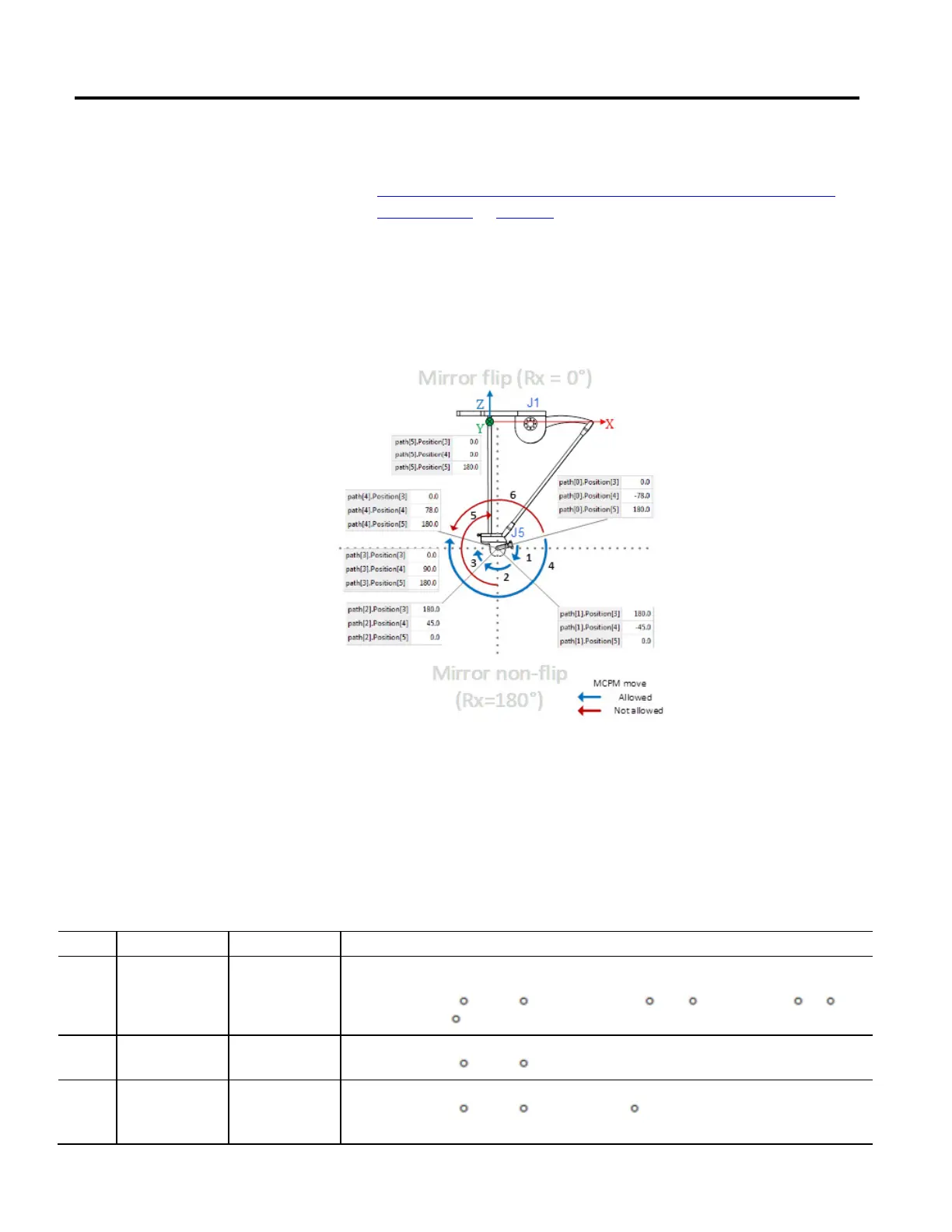
Below is the side view of the Delta J1J2J3J4J5 arm. It illustrates Ry moves using
the absolute position to specify the end of the move.
The blue arrows [1-4] indicate absolute moves that are allowed. The red arrows
[5-6] indicate absolute moves that are not allowed.
The following examples are limited to absolute moves since incremental moves for
orientation axes with mirror image are not impacted like absolute moves. The
absolute orientation for starting and end positions are specified using the notation
[Rx, Ry, Rz]. Also, the examples limit actual motion to the J5 axis (due to Ry) to
demonstrate the mirror image effect on Rx and Rz without generating actual
changes in orientation in those dimensions.
Example Start Region End Region Notes
1 Mirror flip Mirror non-flip
Starting orientation [Rx=0, Ry=(-78), Rz=180], with Motion Coordinated Path Move (MCPM) move to orientation
[Rx=180, Ry=(-45), Rz=0].
The resultant move is +57
on Ry (-57 on J5), and Rx flips from 0 to 180 and Rz flips from 180 to 0 when
Ry crosses the minus -90
boundary.
2 Mirror non-flip Mirror non-flip Starting orientation [Rx=180, Ry=(-45), Rz=0], with MCPM move to orientation [Rx=180, Ry=45, Rz=0].
The resultant move is +90
on Ry (-90 for J5). No boundary is crossed and thus no flip in value for Rx or Rz.
3 Mirror non-flip Mirror flip Starting orientation [Rx=180, Ry=45, Rz=0], with MCPM move to orientation [Rx=0, Ry=90, Rz=180].
The resultant move is +45
on Ry (-45 on J5). The positive 90 boundary cross causes a flip on Rx and Rz.
See Mirror orientation restrictions for more on specifying Ry = 90 orientation.
absolute moves for geometries
with mirror image position
 Loading...

