Geometries with orientation support
182 Rockwell Automation Publication MOTION-UM002F-EN-P - February 2018
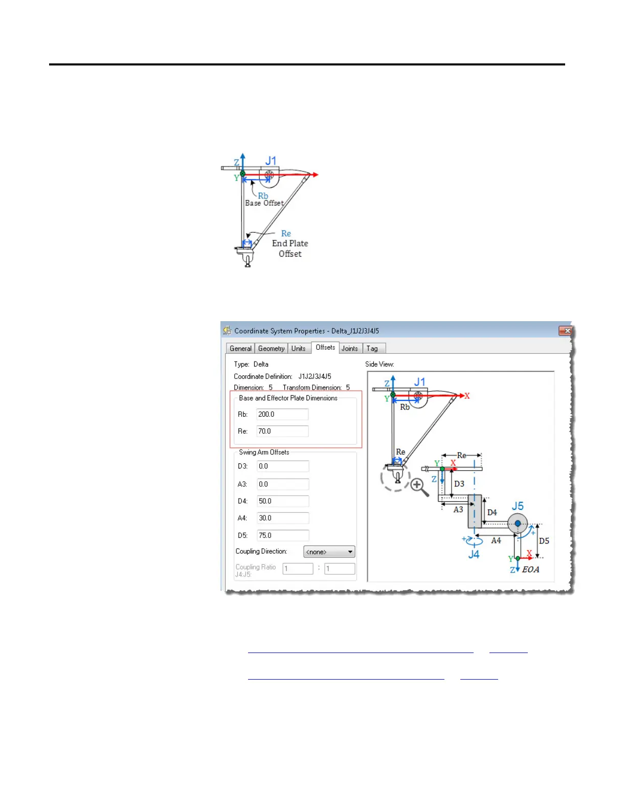
• Re - This offset represents the End plate offset value. Enter the value equal
to the distance from the center of the moving end plate to the lower
spherical joints of the parallel arms (L2).
In the Offsets tab in the Coordinate System Properties dialog box, enter the
base offset and effector plate offset for the 5-axis Delta robot.
See also
Configuration parameters for Delta J1J2J3J4J5 robot on page 180
Swing Arms offsets for Delta J1J2J3J4J5 robot on page 182
In the 5-axis Delta robot configuration, the Joint 4 and Joint 5 axis are configured
using Swing Arm offsets A3, D3, A4, D4, and D5. Denavit - Hartenberg (DH)
notation is used to configure these offset values. Use XYZ axis directions, shown
in the image at end plate center point, as a reference frame to measure the offset
Swing Arm Offsets for Delta
J1J2J3J4J5 robot
 Loading...

