Geometries with orientation support
164 Rockwell Automation Publication MOTION-UM002F-EN-P - February 2018
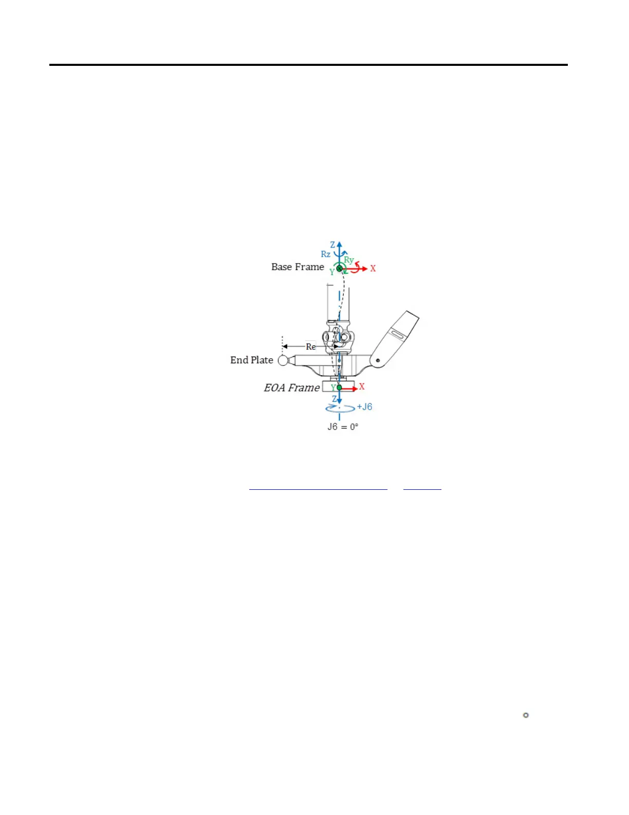
J6 axis of rotation is aligned with the Z axis of Base frame.
• To set the home position for J6 axis, move the J6 axis so that the X axis of
EOA is aligned with the top link (L1) of the arm (J1), that is, X axis of Base
frame.
• +J6 is measured clock wise around the +Z axis at the Base frame.
The following illustration shows the rotation of the axis and its directions for J6
axis.
See also
Calibrate a Delta J1J2J3J6 robot on page 164
Use these steps to calibrate a Delta J1J2J3J6 robot.
To calibrate a Delta J1J2J3J6 robot:
1. Obtain the angle values from the robot manufacturer for J1, J2, J3, and J6 at
the calibration position. Use these values to establish the reference position.
2. Refer to manufacturer’s datasheet to determine if the associated sized motor
contains an internal or external gearbox from the motor to actuation at the
links or Joints to move the robot.
3. On the Scaling tab in the Axis Properties dialog box, in the Transmission
Ration I/O box, set the gear ratio for each axis.
4. In the Scaling box, enter the scaling to apply to each axis (J1, J2, and J3)
such that one revolution around the Link1 (load rev) equals 360
.
Calibrate a Delta J1J2J3J6 robot
 Loading...

