Geometries with no orientation support
80 Rockwell Automation Publication MOTION-UM002F-EN-P - February 2018
Important: Verify that the values for the link lengths, base offsets, and end-effector offsets are entered into the Configuration
Parameters dialog box using the same measurement units.
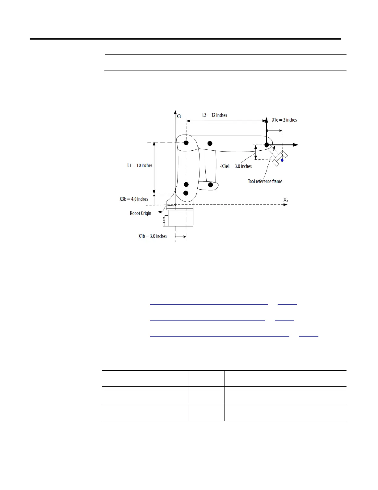
This example illustrates the typical configuration parameters for an Articulated
Dependent robot.
If the robot is two-dimensional, the X3b and X3e are X2b and X2e.
See also
Link lengths for Articulated Dependent robot on page 80
Base offsets for Articulated Dependent robot on page 81
End-Effector Offsets for Articulated Dependent robot on page 82
Link lengths are the rigid mechanical bodies attached at joints.
For an articulated dependent robot with The length of Is equal to the value of the distance between
2 dimensions L1
L2
J1 and J2
J2 and the end-effector
3 dimensions L1
L2
J2 and J3
J3 and the end-effector
Enter the link lengths on the Geometry tab in the Coordinate System
Properties dialog box.
Link lengths for Articulated
Dependent robot
 Loading...

