Geometries with no orientation support
86 Rockwell Automation Publication MOTION-UM002F-EN-P - February 2018
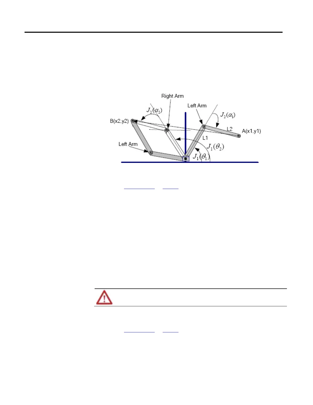
Example: Suppose, you want to move the robot from position A (x1,y1) to
position B (X2,Y2) as shown in th following figure . At position A, the system is in
a left arm solution. When programming a Cartesian move from A (X1,Y1) to B
(X2,Y2), the system moves along the straight line from A to B while maintaining a
left arm solution. If you want to be at position B in a right-arm solution, you must
make a joint move in J1 from θ1 to θ2 and a joint move in J2 from α1 to α2.
See also
Arm solutions on page 83
A singularity occurs when an infinite number of joint positions (mathematical
solutions) exist for a given Cartesian position. The Cartesian position of a
singularity is dependent on the type of the robot geometry and the size of the link
lengths for the robot. Not all robot geometries have singularity positions.
For example, singularities for an Articulated Independent robot occur when:
• The robot manipulator folds its arm back onto itself and the Cartesian
position is at the origin.
• The robot is fully stretched at or very near the boundary of its workspace.
An error condition is generated when a singularity position is reached.
Avoid programming the robot towards a singularity position when programming in Cartesian mode. The velocity of the
robot increases rapidly as it approaches a singularity position and can result in injury or death to personnel.
See also
Arm solutions on page 83
When a robot is programmed to move beyond its work envelope, there is no
mathematical joint position for the programmed Cartesian position. The system
forces an error condition.
position
 Loading...

