Home
Allen-Bradley
Controller
MicroLogix 1400
Allen-Bradley MicroLogix 1400 User Manual
5
of 1
of 1 rating
404 pages
Give review
Manual
Specs
To Next Page
To Next Page
To Previous Page
To Previous Page
Loading...
92
Rockwell Automation
Publication 1766
-UM001I-EN-P
- June 201
5
Chapter 5
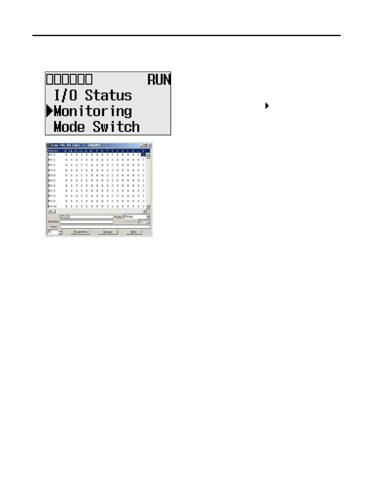
Using the LCD
Cursor Display
Ther
e are two differen
t cursor types
:
Selection cu
rsor (
the sy
mbol “
”) is displayed left to the
selected item.
•
Mov
e cursor w
ith the u
p/dow
n arro
ws
F
ull
blo
ck navig
ation is
shown a
s a f
lash
ing b
lo
ck
:
•
Chang
e
po
si
tion
with
le
ft
/ri
g
ht
arrows
•
Change values with up/down arrows
105
107
Table of Contents
Default Chapter
3
Firmware Revision History
3
Summary of Changes
3
Table of Contents
5
Preface
13
Purpose of this Manual
13
Related Documentation
14
Who Should Use this Manual
13
Common Techniques Used in this Manual
14
Chapter 1
15
Hardware Features
15
Hardware Overview
15
Component Descriptions
16
Micrologix 1400 Memory Module and Built-In Real-Time Clock
16
1762 Expansion I/O
17
Communication Cables
18
Programming
18
Communication Options
19
Agency Certifications
21
Chapter 2
21
Compliance to European Union Directives
21
EMC Directive
21
Low Voltage Directive
22
Install Your Controller
21
Installation Considerations
22
Safety Considerations
23
Hazardous Location Considerations
23
Disconnecting Main Power
24
Safety Circuits
24
Power Distribution
25
Periodic Tests of Master Control Relay Circuit
25
Power Considerations
25
Isolation Transformers
25
Power Supply Inrush
25
Loss of Power Source
26
Input States on Power down
26
Other Types of Line Conditions
26
Master Control Relay
27
Using Emergency-Stop Switches
28
Schematic (Using IEC Symbols)
29
Schematic (Using ANSI/CSA Symbols)
30
Preventing Excessive Heat
27
Installing a Memory Module
30
Using the Battery
31
Connecting the Battery Wire Connector
32
Controller and Expansion I/O Spacing
33
Controller Mounting Dimensions
33
Mounting the Controller
34
DIN Rail Mounting
35
Panel Mounting
36
1762 Expansion I/O Dimensions
37
Mounting 1762 Expansion I/O
37
DIN Rail Mounting
37
Panel Mounting
38
Connecting Expansion I/O
39
Chapter 3 Wiring Requirements
41
Wiring Recommendation
41
Wire Without Spade Lugs
42
Wire with Spade Lugs
42
Wire Your Controller
41
Using Surge Suppressors
43
Recommended Surge Suppressors
44
Grounding the Controller
45
Wiring Diagrams
46
Terminal Block Layouts
47
Sinking and Sourcing Wiring Diagrams
50
1766-L32BWA, 1766-L32AWA, 1766-L32BXB, 1766-L32BWAA, 1766-L32AWAA, 1766-L32BXBA Wiring Diagrams
50
Controller I/O Wiring
52
Minimizing Electrical Noise
52
Wiring Your Analog Channels
53
Analog Channel Wiring Guidelines
54
Minimizing Electrical Noise on Analog Channels
55
Grounding Your Analog Cable
56
Expansion I/O Wiring
56
Digital Wiring Diagrams
56
Analog Wiring
64
Chapter 4
73
Communication Connections
73
Supported Communication Protocols
73
Default Communication Configuration
74
Using the Communications Toggle Functionality
74
Changing Communication Configuration
75
Connecting to the RS-232 Port
77
Making a DF1 Point-To-Point Connection
78
Using a Modem
79
Connecting to a DF1 Half-Duplex Network
82
Connecting to a RS-485 Network
84
DH-485 Configuration Parameters
85
Recommended Tools
87
DH-485 Communication Cable
87
Connecting the Communication Cable to the DH-485 Connector
88
Grounding and Terminating the DH-485 Network
89
Connecting the AIC
90
Cable Selection Guide
91
Recommended User-Supplied Components
94
Safety Considerations
95
Install and Attach the AIC
95
Powering the AIC
96
Connecting to Ethernet
97
Ethernet Connections
98
Using the LCD
99
Chapter 5 Using the LCD Operating Principles
100
Main Menu and Default Screen
103
Operating Buttons
105
Using Menus to Choose Values
105
Selecting between Menu Items
105
Cursor Display
106
Setting Values
107
Operating Principles
100
I/O Status
107
Viewing I/O Status
108
Monitor User Defined Target Files
109
Target User Defined File Number (TUF)
109
Monitoring a Bit File
110
Monitoring Integer Files
114
Monitoring Double Integer Files
119
Monitor Floating Point Files
125
Monitor System Status Files
125
Using the Mode Switch
126
Controller Modes
127
Changing Mode Switch Position
127
Using a User Defined LCD Screen
129
User Defined LCD Screen
130
Configuring Advanced Settings
131
Changing Key in Mode
132
Key in Modes
132
Ethernet Network Configuration
134
Viewing Ethernet Status
134
Configuring the IP Address
136
Configuring the Ethernet Port
140
Configuring Ethernet Protocol Setup
142
Using Communications Toggle Functionality
134
Using Trim Pots
145
Trim Pot Operation
145
Changing Data Value of a Trim Pot
146
Trim Pot Configuration in LCD Function File
147
Error Conditions
147
Viewing System Information
148
Viewing Fault Code
149
Saving/Loading Communication EEPROM
150
Saving Communication EEPROM
150
Loading Communication EEPROM
153
LCD Setup
153
Configuring Contrast Value
154
Configuring the Backlight
155
Protocol Configuration
156
Modbus RTU Slave Node Address
156
Chapter 6
161
Operation at Power-Up and Entering a Run or Test Mode
161
Writing Data to the Real-Time Clock
161
RTC Battery Operation
162
Real-Time Clock Operation
161
Memory Module Operation
162
User Program , User Data, Datalog and Recipe Back-Up
163
Program Compare
163
Data File Download Protection
163
Memory Module Write Protection
163
Removal/Insertion under Power
164
Memory Module Information File
164
Program /Data Download
164
Program /Data Upload
164
Chapter 7 Editing User
165
A Download Is Required before Starting Online Editing
165
Types of Online Editing
166
Edit Functions in Runtime Online Editing
167
Edit Functions in Program Online Editing
167
Appendix A
169
Specifications for Inputs
169
Working Voltage
174
Expansion I/O Specifications
175
Digital I/O Modules
175
Analog Modules
181
Rockwell Automation Publication 1766-UM001I-EN-P - June
182
Appendix B
189
Lithium Battery (1747-BA)
189
Installation
189
Battery Handling
191
Storage
191
Transportation
191
Disposal
193
Micrologix 1400 Replacement Kits
189
Appendix C
195
Controller Status LED Indicators
195
Status Indicators on the LCD
196
I/O Status Indicators on the LCD
197
Normal Operation
197
Error Conditions
197
Understanding the Controller Status Indicators
195
Controller Error Recovery Model
198
Analog Expansion I/O Diagnostics and Troubleshooting
200
Module Operation and Channel Operation
200
Power-Up Diagnostics
200
Critical and Non-Critical Errors
201
Module Error Definition Table
201
Error Codes
202
Calling Rockwell Automation for Assistance
203
Appendix D
205
Install Controlflash Software
205
Prepare the Controller for Firmware Upgrade
206
Preparing for Firmware Upgrade
205
Using Controlflash for Firmware Upgrade
207
Controlflash Error Messages
217
Missing or Corrupt os State
219
Recovering from Missing or Corrupt os State
220
Appendix E
221
Communication Interface
221
DF1 Full-Duplex Protocol
221
DF1 Half-Duplex Protocol
222
DF1 Half-Duplex Operation
222
Considerations When Communicating as a DF1 Slave
224
On a Multi-Drop Link
224
Using Modems with Micrologix Programmable Controllers
224
Communication Protocol
225
DH-485 Configuration Parameters
226
Devices that Use the DH-485 Network
226
Important DH-485 Network Planning Considerations
227
Example DH-485 Connections
231
Ascii
233
Distributed Network Protocol (DNP3)
233
Modbus Communication Protocol
233
Appendix F Channel Configuration for DNP3 Slave
235
Channel 0 and Channel 2 Link Layer Configuration
237
Channel 1 Link Layer Configuration
238
DNP3 Slave Application Layer Configuration
240
Channel 0 and Channel 2 Link Layer Configuration Parameters
242
Channel 1(Ethernet) Link Layer Configuration Parameters
246
DNP3 Slave Application Layer Configuration Parameters
251
Micrologix 1400 Distributed
235
DNP3 Slave Application Layer
264
Function Codes
265
Internal Indications
270
DNP3 Objects and Micrologix 1400 Data Files
270
DNP3 Data Files
274
DNP3 Configuration Files
275
DNP3 Binary Input Object
279
DNP3 Binary Output Object
281
DNP3 Double Bit Binary Input Object
284
DNP3 Counter Object
286
DNP3 Frozen Counter Object
289
DNP3 Analog Input Object
291
DNP3 Analog Output Object
295
DNP3 BCD Object
297
DNP3 Data Set Object
299
Object Quality Flags
309
DNP3 Device Attribute Object
312
Event Reporting
315
Generating Events
315
Control Generating Event
320
Reporting Event by Polled Response
321
Reporting Event by Unsolicited Response
322
Collision Avoidance
324
Time Synchronization
325
Download a User Program Via DNP3 Network
326
Default Directories and Files
327
Generating *.IMG Files Using Rslogix 500/Rslogix Micro
327
Rules for File Authentication
329
Rules for Downloading a User Program
330
Rules for Uploading a User Program
331
Rockwell Automation Publication 1766-UM001I-EN-P - June
331
Rules for Initializing a User Program
332
Rules for Uploading Communication Status Files
332
Starting and Stopping User Programs (Mode Change) Via DNP3
332
Network
332
Initialize User Program
333
Start User Program
333
Stop User Program
333
Diagnostics
334
Diagnostics for Ethernet Channel (Channel 1)
340
Diagnostics for Secure Authentication
347
Function Codes
349
Implementation Table
351
Micrologix 1400 Controllers and Ethernet Communication
365
Appendix G
366
Micrologix 1400 Performance Considerations
366
Micrologix 1400 and PC Connections to the Ethernet Network
367
Ethernet Network Topology
367
Connecting an Ethernet Switch on the Ethernet Network
367
Cables
368
Ethernet Connections
370
Duplicate IP Address Detection
371
Configuring the Ethernet Channel on the Micrologix 1400
372
Configuration Using Rslogix 500/Rslogix Micro Programming
374
Configuration Via BOOTP
374
Using the Rockwell Automation BOOTP/DHCP Utility
375
Software
374
Using a DHCP Server to Configure Your Processor
377
Using Subnet Masks and Gateways
378
Manually Configuring Channel 1 for Controllers on
379
Subnets
379
Micrologix 1400 Embedded Web Server Capability
379
System Loading Calculations
381
Appendix H System Loading Example Calculations
382
System Loading Worksheet
383
Current Loading
383
Calculating Heat Dissipation
385
Other manuals for Allen-Bradley MicroLogix 1400
Instruction Manual
694 pages
5
Based on 1 rating
Ask a question
Give review
Questions and Answers:
Need help?
Do you have a question about the Allen-Bradley MicroLogix 1400 and is the answer not in the manual?
Ask a question
Allen-Bradley MicroLogix 1400 Specifications
General
Brand
Allen-Bradley
Model
MicroLogix 1400
Category
Controller
Language
English
Related product manuals
Allen-Bradley MicroLogix 1100
256 pages
Allen-Bradley micrologix 1500
174 pages
Allen-Bradley MicroLogix 1000
422 pages
MicroLogix 1000 PLC
2 pages
Allen-Bradley Micro800
78 pages
Allen-Bradley Micro820
184 pages
Allen-Bradley Micro850
24 pages
Allen-Bradley Micro830
354 pages
Allen-Bradley Micro810
102 pages
Allen-Bradley Micro870
354 pages
Allen-Bradley 1756-M08SE
236 pages
Allen-Bradley PowerFlex 525
244 pages

 Loading...


