Rockwell Automation Publication 1766-UM001I-EN-P - June 2015 267
MicroLogix 1400 Distributed Network Protocol (DNP3) Appendix F
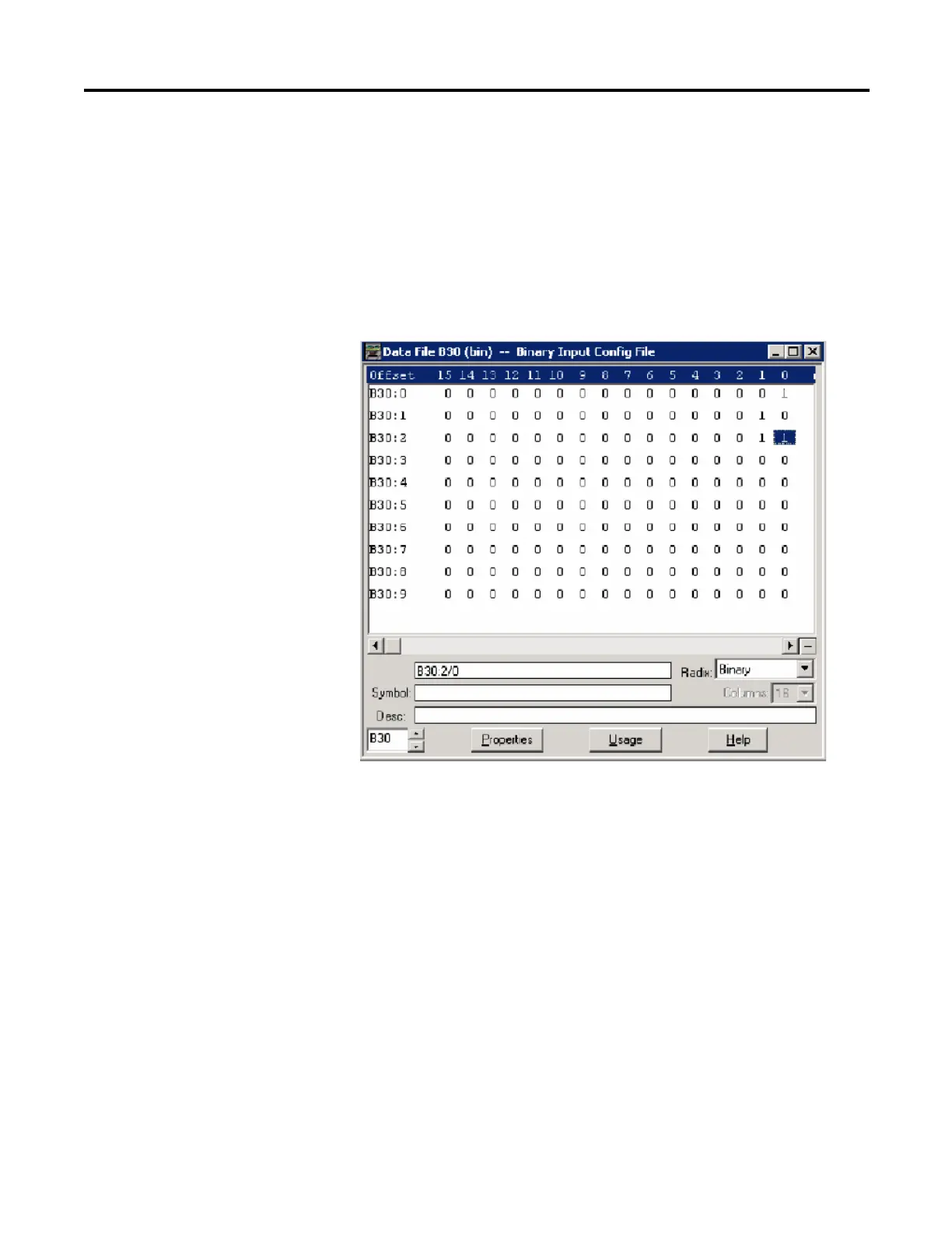
As an example, a Binary Input Config File shown below has 10 elements. B30:0/0
and B30:0/1 can be configured for Class Level 0, 1, 2 or 3 for DNP3 Index 0 to
15 of the Binary Input Object File. B30:1/0 and B30:1/1 can be configured for
Class Level for DNP3 Index 16 to 31 of the Binary Input Object File. Default
Class Level is 0. Any other bits are reserved.
Class Level of Index 0 to 15 is 1(B30:0/0 and B30:0/1), Class Level of Index 16
to 31 is 2(B30:1/0 and B30:1/1), Class Level of Index 32 to 47 is 3(B30:2/0 and
B30:2/1), and Class Level of other Indexes are 0.
DNP3 Binary Output Object
The supported object group and variations are listed in this section. The
MicroLogix 1400 responds with the default group and variation when the DNP3
Master requests to read the object with Any Variation.
Binary Output Static Objects:
• g10v0 - Binary Output - All Variations
• g10v2 - Binary Output - Output status with flags (default)
Binary Output Command Objects:
• g12v1 - Binary Command - Control relay output block (CROB)
Related Object File Number:
• Binary Output Object File Number

 Loading...


