18 Rockwell Automation Publication 1766-UM001I-EN-P - June 2015
Chapter 2 Install Your Controller
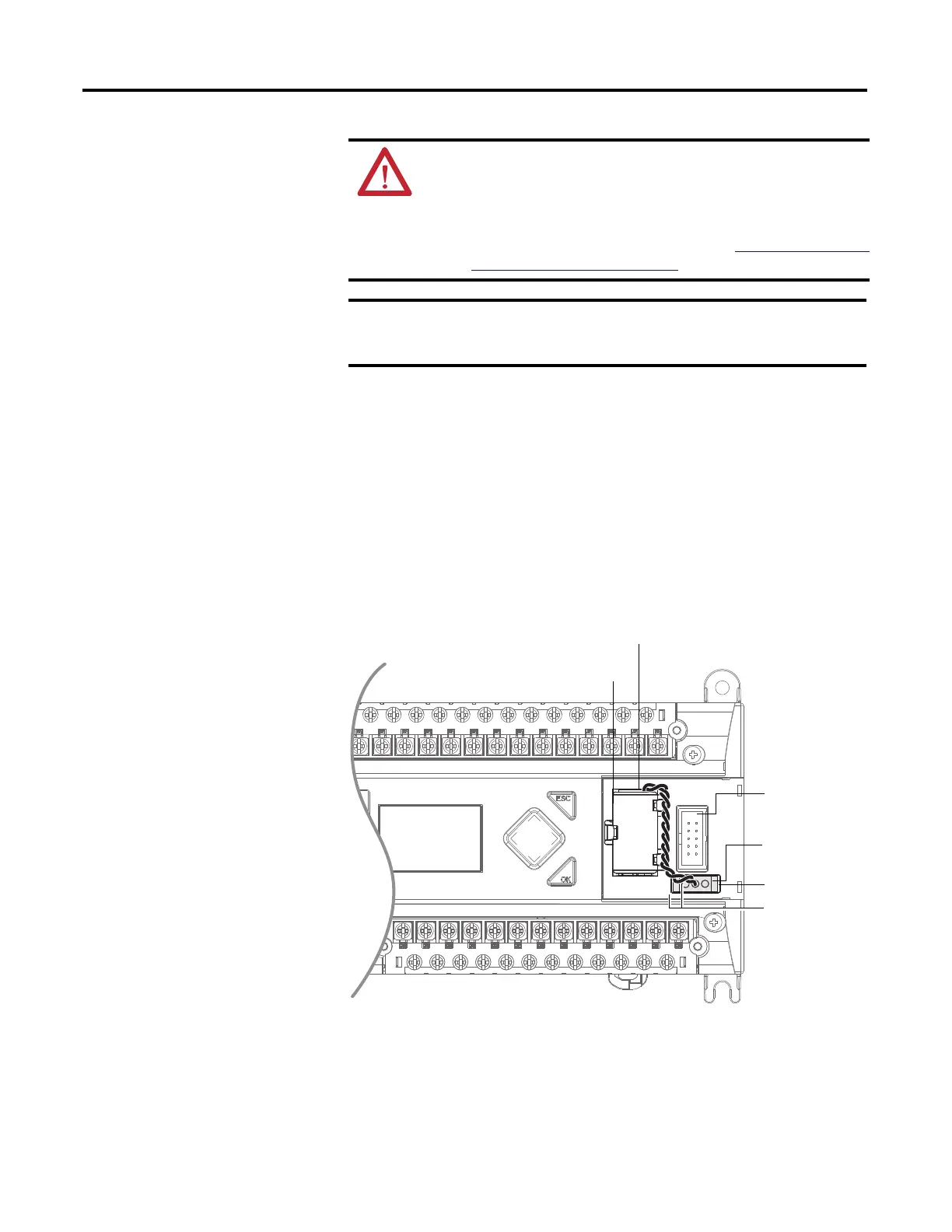
Connecting the Battery Wire Connector
Follow the procedure below to connect the battery wire connector to the battery
connector.
1. Insert the replaceable battery wire connector into the controller’s battery
connector.
2. Secure the battery connector wires so that it does not block the 1762
expansion bus connector as shown below
.
WARNING: When you connect or disconnect the battery an
electrical arc can occur. This could cause an explosion in hazardous
location installations. Be sure that the area is nonhazardous before
proceeding.
For Safety information on the handling of lithium batteries, including
handling and disposal of leaking batteries, see Guidelines for Handling
Lithium Batteries, publication AG 5-4.
When the controller’s Battery Low indicator is set (displayed as a solid
rectangle) with the battery wire connector connected, you should
install a new battery immediately.
1762 I/O expansion
bus connector
Battery wires
twisted pair
Battery
Battery wire
connector
Battery connector
44522
Battery compartment

 Loading...


