4 Rockwell Automation Publication 1766-UM001I-EN-P - June 2015
Chapter 1 Hardware Overview
Communication Cables
Use only the following communication cables with the MicroLogix 1400
controllers. These cables are required for Class I Div. 2 applications.
• 1761-CBL-AM00 Series C or later
• 1761-CBL-AP00 Series C or later
• 1761-CBL-PM02 Series C or later
• 1761-CBL-HM02 Series C or later
• 2707-NC9 Series C or later
• 1763-NC01 Series A or later
• 1747-CP3 Series A or later
Programming
Programming the MicroLogix 1400 controller is done using
RSLogix 500/RSLogix Micro, Revision 8.10.00 or later for Series A controllers
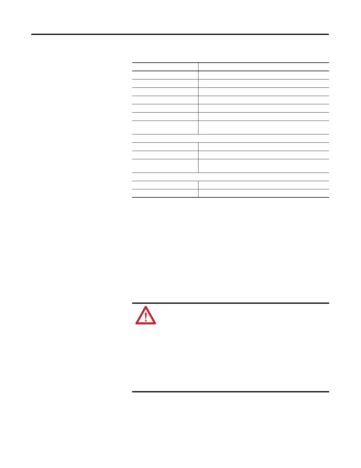
1762-OB16 16-Point Sourcing 24V DC Output Module
1762-OB32T 32-Point Sourcing 24V DC Output Module
1762-OV32T 32-Point Sinking 24V DC Output Module
1762-OW8 8-Point AC/DC Relay Output Module
1762-OW16 16-Point AC/DC Relay Output Module
1762-OX6I 6-Point Isolated AC/DC Relay Output Module
1762-IQ8OW6 8-Point Sink/Source 24V DC Input and 6-Point AC/DC Relay Output
Module
Analog
1762-IF4 4-Channel Voltage/Current Analog Input Module
1762-OF4 4-Channel Voltage/Current Analog Output Module
1762-IF2OF2 Combination 2-Channel Input 2-Channel Output Voltage/Current
Analog Module
Temperature
1762-IR4 4-Channel RTD/Resistance Input Module
1762-IT4 4-Channel Thermocouple/mV Input Module
Expansion I/O
Catalog Number Description
ATTENTION: UNSUPPORTED CONNECTION
Do not connect a MicroLogix 1400 controller to another MicroLogix
family controller such as MicroLogix 1000, MicroLogix 1200,
MicroLogix 1500, or the network port of a 1747-DPS1 Port Splitter
using a 1761-CBL-AM00 (8-pin mini-DIN to 8-pin mini-DIN) cable or
equivalent.
This type of connection will cause damage to the RS-232/485
communication port (Channel 0) of the MicroLogix 1400 and/or the
controller itself. The communication pins used for RS-485
communications on the MicroLogix 1400 are alternately used for
24V power on the other MicroLogix controllers and the network
port of the 1747-DPS1 Port Splitter.

 Loading...


