260 Rockwell Automation Publication 1766-UM001I-EN-P - June 2015
Appendix F MicroLogix 1400 Distributed Network Protocol (DNP3)
DNP3 Data Files
Basically, the index number of DNP objects of each type is evaluated by the
firmware automatically per the number of elements. For example, if a Binary
Input object file was configured as an element, the highest index number of the
Binary Input object is 15. The index number can only be increased by 16. If a
Double-Bit Binary Input object file was configured as an element, the highest
index number of the Double-Bit Binary Input object is 7. The index number can
only be increased by 8.
As another example, if a 16-bit Analog Input object file was configured as an
element, the highest index number is 1. Except for Binary and Double-Bit Binary
type objects, the index number can be increased by 1.
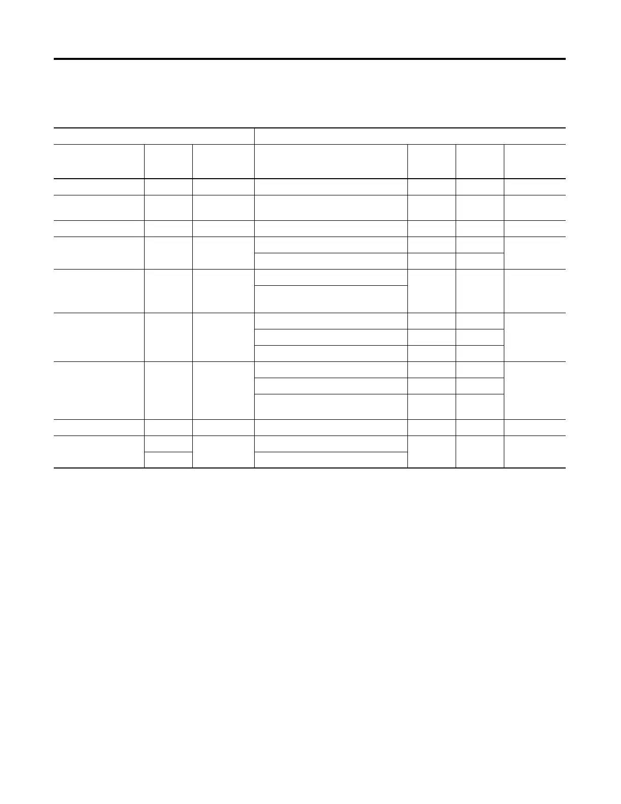
Relationship between DNP3 object database and MicroLogix data files
DNP Objects Micrologix Data Files
Object Name Related
Groups
Maximum
Configurable
Index
File name for Data File Type File
Number
Maximum
Configurable
Elements
Binary Input Object 1, 2 4096 Binary Input Object File Only B file 3, 9 to 255 256
Double Bit Binary Input
Object
3, 4 2048 Double Bit Binary Input Object File Only B file 3, 9 to 255 256
Binary Output Object 10, 12 4096 Binary Input Object File Only B file 3, 9 to 255 256
Counter Object 20, 22 256 16-bit Counter Object File Only N file 7, 9 to 255 256
32 bit Counter Object File Only L file 9 to 255
Frozen Counter Object 21, 23 reflection of
Counter Object
which was
configured
reflection of 16-bit Counter Object File - - -
reflection of 32-bit Counter Object File
Analog Input Object 30, 32 256 16-bit Analog Input Object File Only N file 7, 9 to 255 256
32-bit Analog Input Object File Only L file 9 to 255
Short Floating Point Analog Input Object File Only F file 8, 9 to 255
Analog Output Object 40, 41 256 16-bit Analog Output Object File Only N file 256
32-bit Analog Output Object File Only L file 9 to 255
Short Floating Point Analog Output Object
File
Only F file 8, 9 to 255
BCD Object 101 256 Small BCD Object File Only N file 7, 9 to 255 256
Data Set Object(In
Series B)
85, 87, 88 10 Data Set Prototypes Object File Only N file 7, 9 to 255 10
86, 87, 88 Data Set Descriptors Object File

 Loading...


