74 Rockwell Automation Publication 1766-UM001I-EN-P - June 2015
Chapter 4 Communication Connections
When cutting cable segments, make them long enough to route them from one
AIC+ to the next, with sufficient slack to prevent strain on the connector. Allow
enough extra cable to prevent chafing and kinking in the cable.
Use these instructions for wiring the Belden #3106A or #9842 cable. (See Cable
Selection Guide on page 77 if you are using standard Allen-Bradley cables.)
Connecting the Communication Cable to the DH-485 Connector
Single Cable Connection
When connecting a single cable to the DH-485 connector, use the following
diagram.
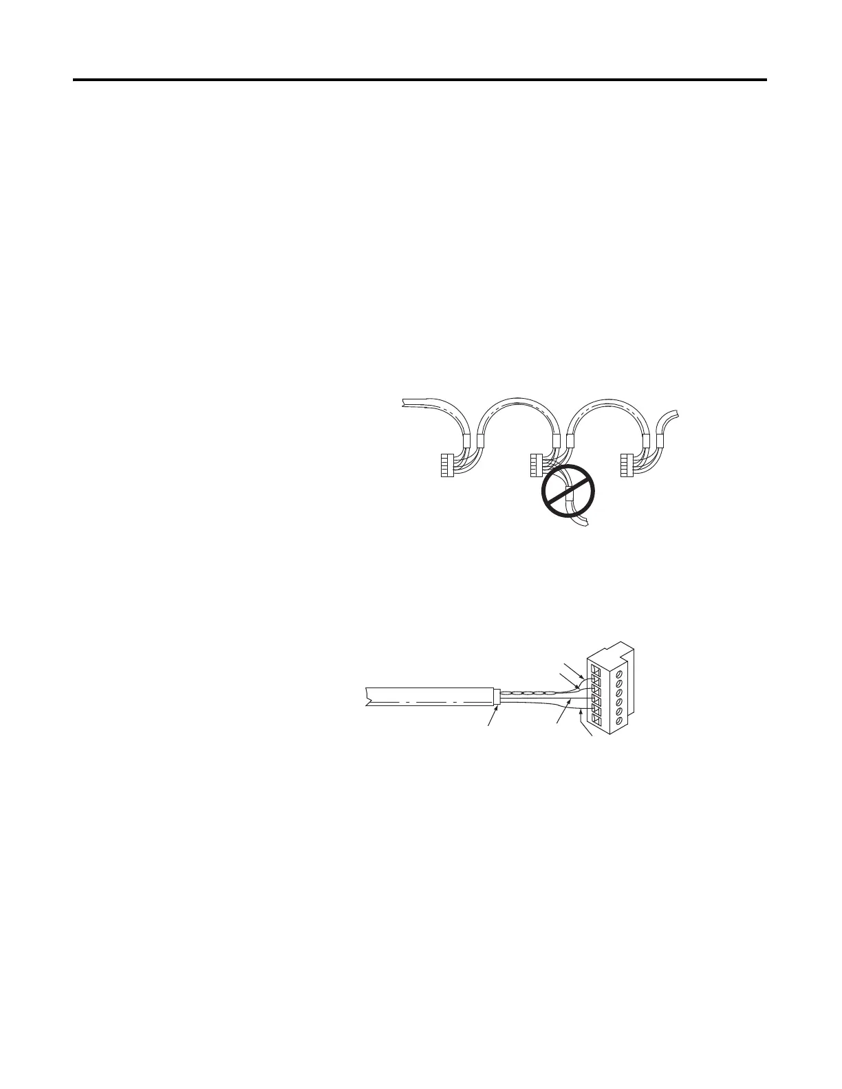
A daisy-chained network is recommended. Do not make the incorrect
connection shown below:
Belden #3106A
or #9842
Belden #3106A or
#9842
Belden #3106A or
#9842
Connector
Connector
Connector
Incorrect
Orange with White Stripes
White with Orange Stripes
Shrink Tubing Recommended
Blue (#3106A) or
Blue with White
Stripes (#9842)
Drain Wire
6 Termination
5 A
4 B
3 Common
2 Shield
1 Chassis Ground

 Loading...


