EasyManuals Logo
Home>Allen-Bradley>Controller>MicroLogix 1400

Allen-Bradley MicroLogix 1400 User Manual

Allen-Bradley MicroLogix 1400
404 pages
To Next Page IconTo Next Page
To Previous Page IconTo Previous Page
Page #53 background imageLoading...
Page #53 background image
Rockwell Automation Publication 1766-UM001I-EN-P - June 2015 39
Wire Your Controller Chapter 3
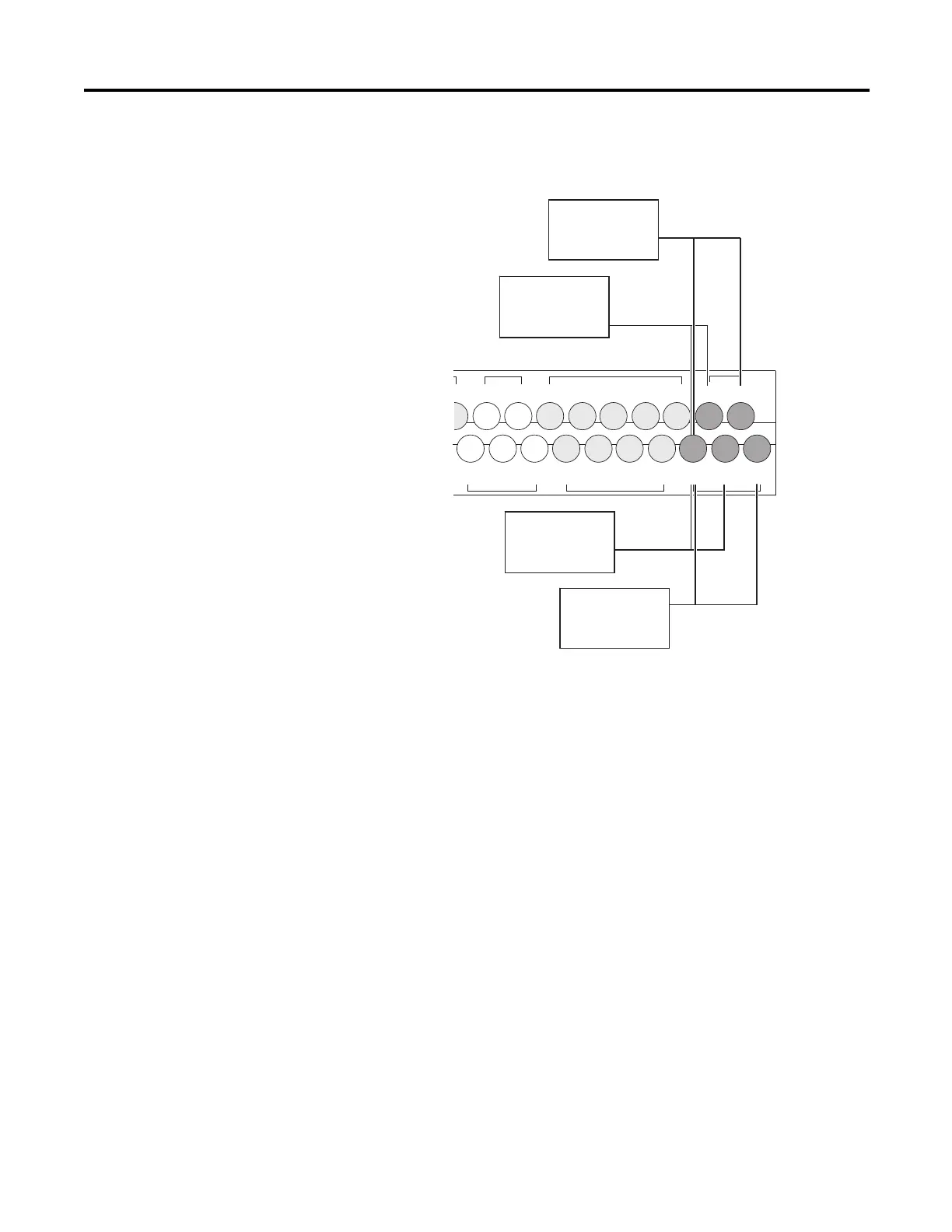
Wiring Your Analog
Channels
Analog input circuits can monitor voltage signals and convert them to serial
digital data.
The controller does not provide loop power for analog inputs. Use a power
supply that matches the transmitter specifications as shown.
The analog output can support a voltage function as shown in the following
illustration.
IV0(+) IV2(+)
IV1(+) IV3(+)
/7
COM 2
I/8 I/10
I/9 I/11
COM 3
I/13 I/15 I/17 I/19
I/12 I/14 I/16 I/18
COM
ANA
Input Terminal Block
Sensor 2 (V)
Voltage
44529
Sensor 3
(V) Voltage
Sensor 0 (V)
Voltage
Sensor 1 (V)
Voltage

Table of Contents

Other manuals for Allen-Bradley MicroLogix 1400

Questions and Answers:

Question and Answer IconNeed help?

Do you have a question about the Allen-Bradley MicroLogix 1400 and is the answer not in the manual?

Allen-Bradley MicroLogix 1400 Specifications

General IconGeneral
BrandAllen-Bradley
ModelMicroLogix 1400
CategoryController
LanguageEnglish

Related product manuals